System for controlling a vehicle with determination of the speed thereof relative to the ground

a technology of a vehicle and a speed determination, applied in the field of land vehicles, can solve the problems of inability to monitor the behaviour of the vehicle by the system, the proposed extrapolation technique is unsuitable for the monitoring of the vehicle behaviour by the system, and the measurement from the accelerometer is affected by errors, so as to achieve the effect of reliable estimation of the linear speed of the vehicl

Inactive Publication Date: 2010-10-07
MICHELIN RECH & TECH SA +1
View PDF24 Cites 40 Cited by
  • Summary
  • Abstract
  • Description
  • Claims
  • Application Information

AI Technical Summary

Benefits of technology

[0016]In light of these developments and of the state of the art that has just been described, the subject of the present invention is thus a system capable of supplying, at each instant, a reliable estimation of the linear speed of the vehicle, notably to make it possible to control certain parameters of the behaviour of its wheels with respect to the ground. It is particularly well-suited to vehicles in which the driving and braking of each driving wheel of the vehicle are fully or totally obtained from one and the same electric machine, specific to that wheel.

Problems solved by technology

Thus, simply combining the measurement signals produced by the individual wheel sensors is insufficient to obtain a valid determination of the speed of the vehicle relative to the ground, which is sufficiently accurate, dynamic and reliable for a real-time assessment of the behaviour of the vehicle and its wheels.
The computation is no longer valid outside these limits for supplying a measurement of the slip proper.
Independently of any discussion regarding the applicability of the proposed method to all situations, the proposed extrapolation technique is unsuited to a monitoring of the behaviour of the vehicle by the system that is continuous, or during transitional phases that can last a few seconds, unlike the case of discontinuous operation, for example in an antilock braking control case, in which the system normally allows for a resumption of road grip involving a new valid measurement of the speed, after a fraction of a second following the detection of a fault.
In practice, the measurement from the accelerometer is affected by the error due to the component of the terrestrial acceleration according to the possible slope of the ground on which the vehicle is moving.
It follows that, on the one hand, the validity tests on the longitudinal speed measurements proposed for the wheels do not appear sufficiently accurate to provide reliable indications concerning the vehicle speed and that, on the other hand, the proposed method for testing the consistency of the accelerations and, in the event of a consistency fault, for determining the speed is affected by errors incompatible with continuous operation during periods that can extend to several seconds, for example in the case of prolonged emergency braking (or pronounced acceleration).
Determining the overall speed of a vehicle relative to the ground therefore remains an essential issue in developing vehicle behaviour control systems.
Furthermore, this issue is particularly important in the case of an electric vehicle for which not only the traction but also braking are fully and directly derived from the electrical energy.
Furthermore, the linear speed of the vehicle at the level of a given wheel cannot necessarily be deduced simply from the angular speed measured on said wheel because, notably, of the factors due to the dynamic behaviour of the vehicle, such as slips induced by the braking or acceleration forces in the area of contact of these wheels with the ground.

Method used


Image

  • System for controlling a vehicle with determination of the speed thereof relative to the ground
  • System for controlling a vehicle with determination of the speed thereof relative to the ground
  • System for controlling a vehicle with determination of the speed thereof relative to the ground

Examples


Embodiment Construction

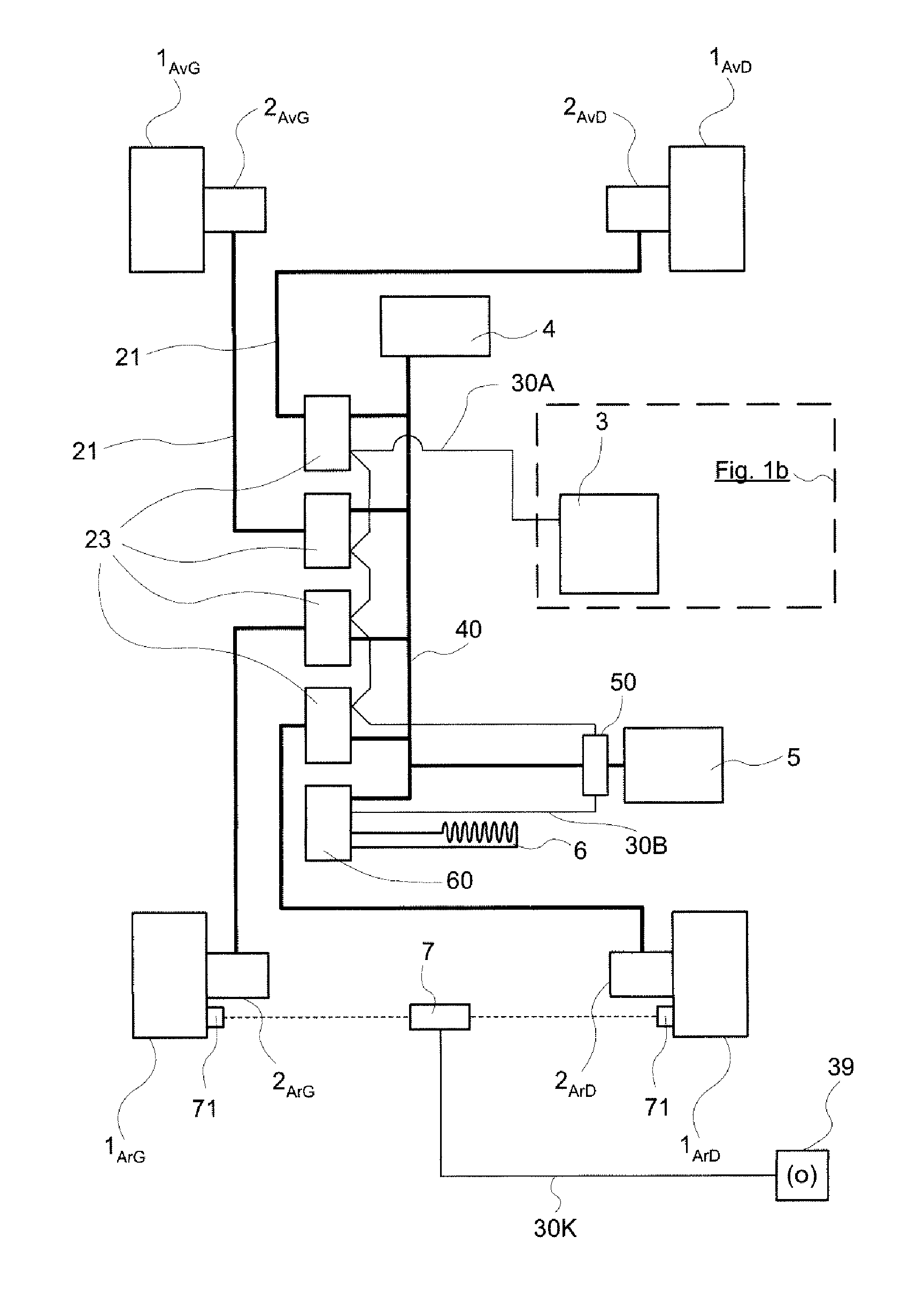
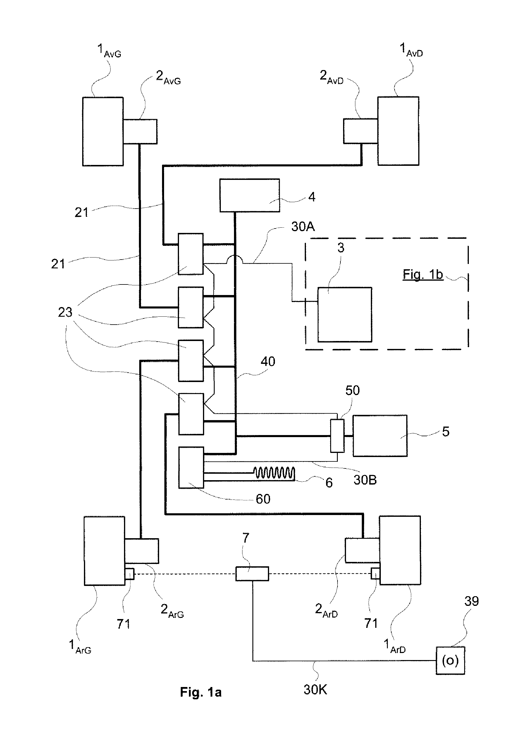
[0050]FIG. 1a diagrammatically represents a vehicle with four wheels 1AvG, 1AvD, 1ArG and 1ArD. The wheels are denoted 1AvG for the front left wheel, 1AvD for the front right wheel, 1ArG for the rear left wheel and 1ArD for the rear right wheel. Each wheel is equipped with an electric machine that is mechanically coupled to it. The electric machines 2AvG, 2AvD, 2ArG and 2ArD can be seen. Hereinafter, the indices specifically designating the position of the wheel 1 or of the electric machine 2 in the vehicle will not be repeated when it adds nothing to the clarity of the explanation. The traction electric machines 2 are three-phase machines of self-controlled synchronous type. They are each equipped with an angular position sensor of resolver type 11 (FIG. 3) incorporated behind the machine and are each controlled by a respective electronic wheel control module 23 to which they are connected by electric power lines 21.

[0051]The electronic wheel control modules 23 are designed to cont...


PUM


Abstract

A system for controlling the behaviour of a vehicle relative to the ground is described wherein the linear ground speed of a vehicle that has at least two wheels (1) each equipped with a sensor suitable for supplying a measurement that is a function of the rotation of said wheel is determined at each instant. The system comprises a circumferential speed indicator (101, 102) for each wheel (1) based on the measurement from the corresponding sensor (11) and a system for diagnosing characteristic parameters of the instantaneous condition of said wheels to validate the use of the circumferential speed Vr measured for each of these wheels to produce an estimation of the instantaneous speed Vv of the vehicle relative to the ground. The diagnostic system notably comprises a means (109) of diagnosing loss of road grip of a wheel as a function of its instantaneous acceleration, a means (107) of diagnosing the validity of the wheel speed indication based on a measurement of the road grip coefficient of the wheel and a means (113) of diagnosing the maintaining or restoration of road grip of the wheel as a function of a determination of its slip. A vehicle speed indicator (119) produces an estimation of the vehicle speed relative to the ground as a function of indications that are not rejected on completion of the diagnoses carried out. The invention also targets the application of this speed estimation system to the determination of the instantaneous slip when rolling of the wheels of a vehicle, each coupled to an individual electric machine and to the control of the torque applied to each of these wheels as a function of this slip to improve the behaviour of the vehicle.

Description

FIELD OF THE INVENTION[0001]The present invention relates to land vehicles, in particular road vehicles. It targets in particular the techniques for controlling such vehicles and the determination of their speed relative to the ground for this purpose, in order to adjust the parameters that determine this behaviour and improve running conditions and safety. It is particularly well suited to the case where the movement of the vehicle on the ground is controlled by one or more specific electric machines coupled to a driving wheel to apply to it a driving torque or braking torque according to requirements.STATE OF THE ART[0002]Electric vehicle proposals have progressed a great deal in recent years. The U.S. Pat. No. 5,418,437 can, for example, be cited which describes a four-wheel vehicle, of series hybrid type, each wheel being driven by an electric machine that is specific to it, a controller making it possible to control the motors incorporated in the wheel and handling the manageme...

Claims


Application Information

Patent Timeline
Patent Type & Authority Applications(United States)
IPC IPC(8): B60T8/172B60W40/06B60W40/10
CPCB60L3/10Y02T10/7275B60L2240/16B60L2240/461B60L2240/465B60T8/172B60T8/1755B60T2250/04B60W40/06B60W40/072B60W40/076B60W40/101B60W40/105B60W2520/105B60W2520/28B60W2550/148B60W2710/18B60W2720/28B60L2200/26B60L15/2009Y02T10/72B60W2552/40Y02T10/64
Inventor LINDA, JEAN-LOUISWALSER, DANIEL
Owner MICHELIN RECH & TECH SA
Why Eureka
Try Eureka