Partially plug-less dpf

a filter and particulate matter technology, applied in the field of ceramic filters, can solve the problems of crack generation, decrease purification efficiency, increase pressure loss, etc., and achieve the effects of improving regeneration limit, reducing the amount of soot (particulate matter) deposited, and raising the passage flow ra

Inactive Publication Date: 2010-10-14
NGK INSULATORS LTD
View PDF29 Cites 10 Cited by
  • Summary
  • Abstract
  • Description
  • Claims
  • Application Information

AI Technical Summary

Benefits of technology

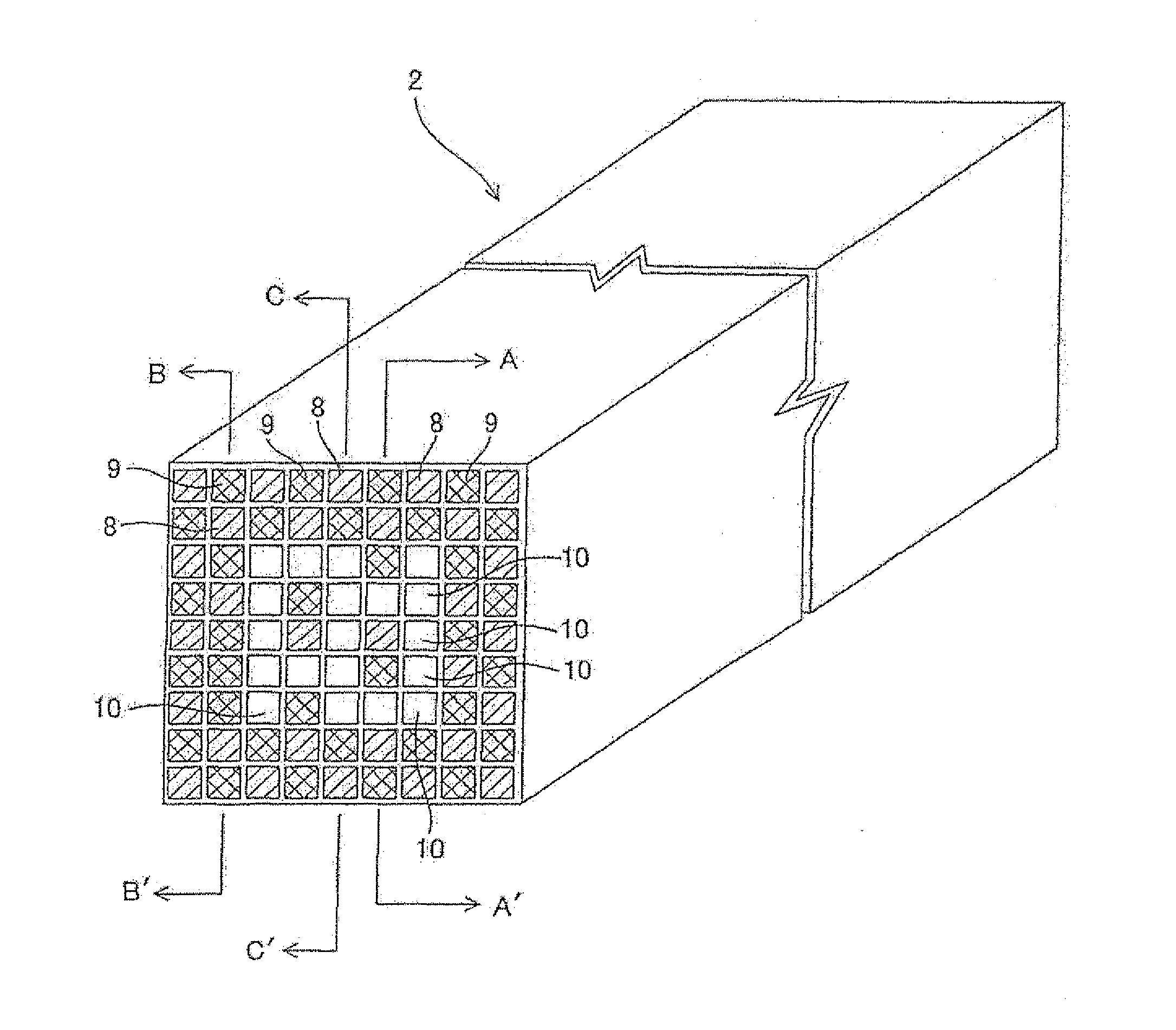
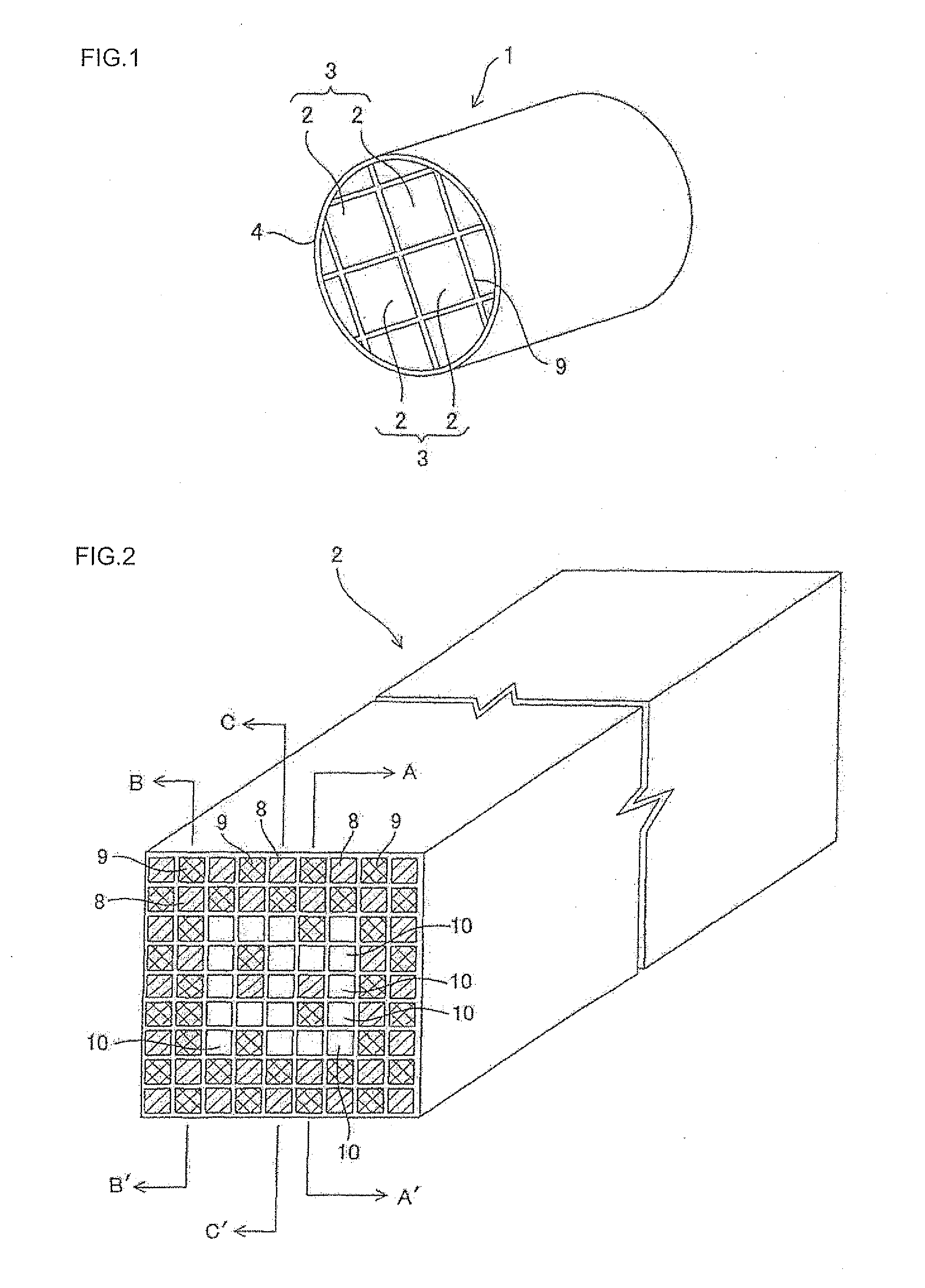
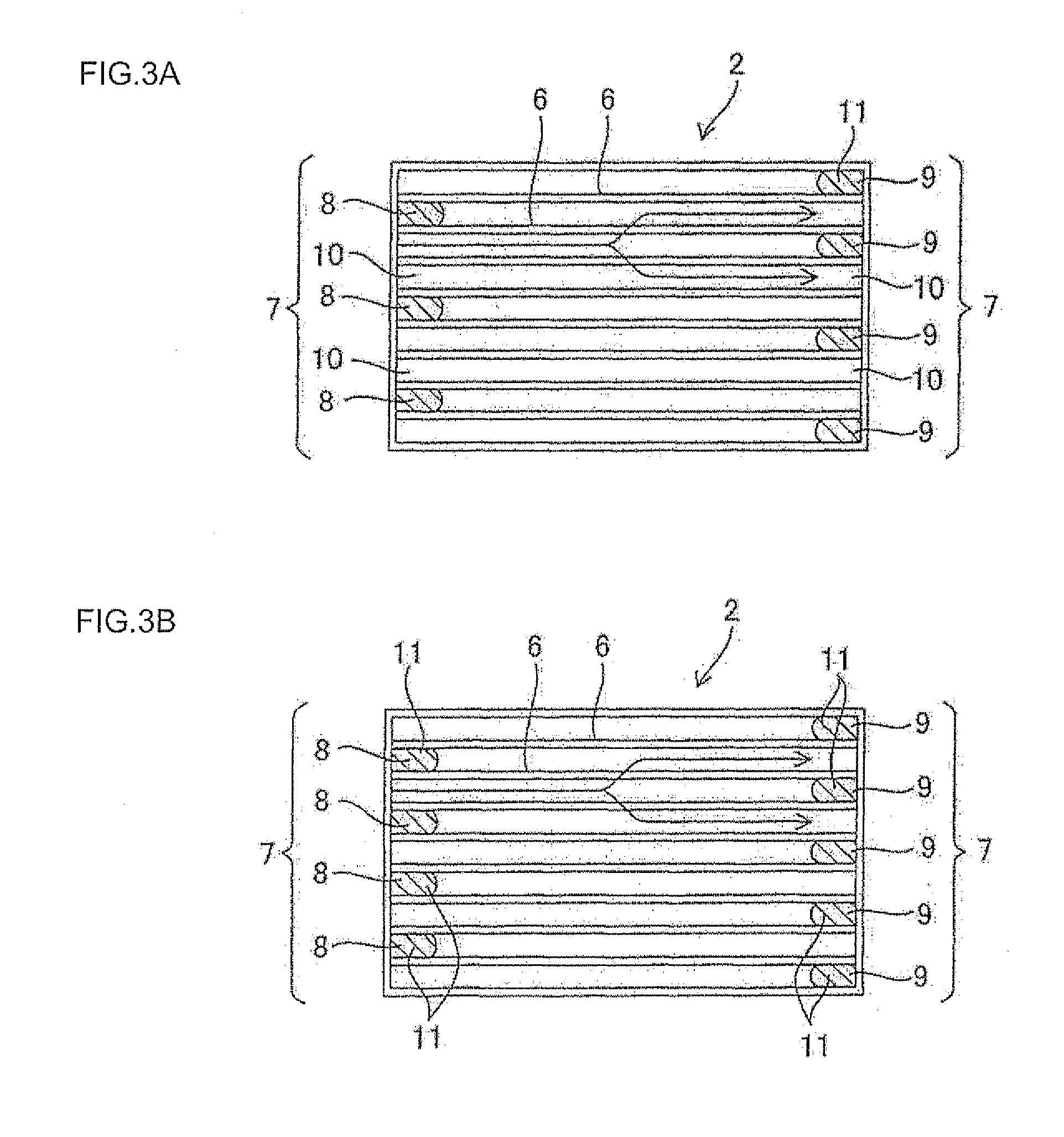
[0038]According to the present invention, there is exhibited excellent effects capable of providing a ceramic filter capable of controlling extraordinary temperature rise in the inside portion upon regeneration by reducing the amount of soot (amount of particulate matter) deposited by raising the passage flow rate in the through-cells by arranging through-cells having the unplugged inlet cell and outlet cell in a plurality of circulation holes provided in the honeycomb segment formed of a plurality of cells and capable of realizing both the improvement in regeneration limit and the response to PM emission and a method for manufacturing a ceramic filter.

Problems solved by technology

In such a DPF, by continuous purification of exhaust gas, soot deposits in the circulation holes, and pressure loss increases with the passage of time to decrease purification efficiency.
During such regeneration of honeycomb segments, the maximum temperature on the outlet side becomes durable temperature or more of the honeycomb segments to cause problems of crack generation in a honeycomb segment and / or deterioration of a loaded catalyst.
Above all, a DPF having a segment structure has a problem in controlling the maximum temperature upon regeneration.
Therefore, the peculiar temperature distribution may cause deformation due to thermal expansion in the outlet end face of a segment and / or application of tensile stress to cause a problem of easy crack generation in the outlet end face.
Therefore, the maximum temperature upon regeneration cannot be suppressed sufficiently, and it does not serve as a sufficient countermeasure against the problems of a deformation due to thermal expansion of the segment and easily crack generation.
However, the trapping efficiency is prone to vary due to deposition of particulate matter, and the Patent Document 3 shows a unitarily formed honeycomb structure.
Therefore, it is not sufficient for the problems of the DPFs having a segment structure.
In this constitution where two or more substrates are arranged in series, as the regeneration is repeated, the PM deposited in a downtown DPF cannot be combusted completely to make pressure loss very high, and extraordinary combustion may be caused in the downstream DPF upon regeneration after repetition.
Thus, the problems have not been solved.

Method used


Image

  • Partially plug-less dpf
  • Partially plug-less dpf
  • Partially plug-less dpf

Examples


example

[0145]The regeneration test at an engine bench was performed, and, with evaluating temperature where a crack is generated, PM emission was evaluated in a vehicle to consider the optimum design in view of the temperature reduction effect by increase of the through-cells and PM emission deterioration (decrease in trapping efficiency). The specific test method was as follows:

[0146](Regeneration Test)

[0147]In the first place, a DPF is mounted on a 2.0 L diesel engine, and a predetermined amount of soot was deposited, followed by driving at 2000 rpm×50 Nm. Next, the DPF inlet gas temperature was raised to 650° C. by post-injection. When the pressure loss in front and at the back of the DPF started to fall, the post-injection was stopped, and the engine driving state was made to be an idle state. At that time, since the oxygen content rapidly increased, and the flow rate was decreased, the DPF internal temperature rapidly rose, and a crack was generated in the DPF outlet end face when the...


PUM

PropertyMeasurementUnit
lengthaaaaaaaaaa
lengthaaaaaaaaaa
diameteraaaaaaaaaa

Abstract

There is provided a ceramic filter capable of controlling extraordinary rise of the internal temperature upon regeneration by reducing an amount of deposited soot (particulates) by increasing a passage flow rate in the through-cells and realizing improvement of the regeneration limit and correspondence of PM emission and a method for manufacturing a ceramic filter. A plurality of circulation holes 7 are formed in the honeycomb segment 2, and the cells are constituted as inlets and/or outlets of the circulation holes 7 and contain a plurality of honeycomb segments 2 bonded to one another. Each honeycomb segment 2 includes a first inflow holes 8, a second inflow holes 9, and as a part at least through-cells 10 formed to extend through in such a manner that fluid can be discharged from the inlet to the outlet of the cells without being plugged at the inlet and the outlet of the cell.

Description

TECHNICAL FIELD[0001]The present invention relates to a ceramic filter used for a DPF (diesel particulate filter) and other trapping filters. The filter traps and removes particulate matter (particulates) such as soot (soot) contained in exhaust gas from a diesel engine or the like.BACKGROUND ART[0002]A DPF is described in JP-A-56-129020. After a plurality of porous honeycomb segments made of ceramic such as silicon carbide are bonded together by means of a bonding layer of segments, the periphery is covered with a coating material layer. The DPF is disposed in an exhaust gas system of a diesel engine and used for purifying exhaust gas.[0003]Each of the honeycomb segments in the aforementioned DPF is partitioned by porous partition walls and has a large number of circulation holes extending through in the axial direction. Adjacent circulation holes have an alternately plugged end. That is, the circulation hole is open in one side end portion and plugged in the other side end portion...

Claims


Application Information

Patent Timeline
Patent Type & Authority Applications(United States)
IPC IPC(8): B01D39/20C04B35/64
CPCB01D46/0001B01D46/2451B01D46/2455B01D46/2459B01D46/247B01D2046/2481Y02T10/20B01D2046/2492B01D2046/2496B01D2279/30F01N3/0222F01N2330/30B01D2046/2485Y10S55/05Y02T10/12B01D46/2494B01D46/249B01D46/2486B01D46/2498B01D46/2484B01D46/2478
Inventor MIZUTANI, TAKASHI
Owner NGK INSULATORS LTD
Why Eureka
Try Eureka