Method and a vehicle system for ensuring the functionality of a brake assembly and a vehicle comprising such system

a brake assembly and vehicle system technology, applied in the direction of fluid actuated drum brakes, hoisting equipment, instruments, etc., can solve the problems of increased replacement cost of the owner of the vehicle, reduced frictional force between, and increased displacement along the disk's rotation axis, etc., to reduce the heating increase the temperature of the brake assembly, and reduce the braking effort

Inactive Publication Date: 2010-10-14
VOLVO LASTVAGNAR AB
View PDF11 Cites 17 Cited by
  • Summary
  • Abstract
  • Description
  • Claims
  • Application Information

AI Technical Summary

Benefits of technology

[0020]Thus, if the temperature of a portion of the brake assembly is high the portion may be cooled by discharging air onto it. Since the vehicle system of the present invention uses exhaust air for cooling the portion of the brake assembly, the actuating means of the compressed air system is imparted an actuation and a retraction thus generating the exhaust air needed. Moreover, an increased temperature of a brake assembly is generally obtained during a period of continuous braking. As such, in particular if the compressed air system is part of a brake system acting on the heated brake assembly, the sequence above will in itself reduce the heating of the brake assembly, since the sequence involves a step of retracting the actuator which in this case is a bra

Problems solved by technology

As another example of brake impairment, dirt or fragments from the brake assembly itself (i.e. brake dust) may be present on the rotating member and/or friction member resulting in an uneven and/or reduced contact between the two components which may result in a reduced frictional force between the rotating member and the friction member.
Additionally, an uneven contact between the two components may necessitate the need for a premature replacement of at least one of the two components with a resulting additional replacement cost for the owner of the vehicle.
However, should dirt and/or fragments from the brake assembly be present between the brake disk and the brake assembly, displacement along the disk's axis of rotation may be impaired.
However, the '631 device have some disadvantages.
Naturally, this results in an increased energy consumption of a vehicle onto which the '631 device is mounted.
Such additional control arrangements will naturally increase the cost and complexity of vehicle onto which the '631 device is mounted.
Should the adjusting arrangement mal

Method used


Image

  • Method and a vehicle system for ensuring the functionality of a brake assembly and a vehicle comprising such system
  • Method and a vehicle system for ensuring the functionality of a brake assembly and a vehicle comprising such system
  • Method and a vehicle system for ensuring the functionality of a brake assembly and a vehicle comprising such system

Examples


Embodiment Construction

[0035]The invention will, in the following, be exemplified by embodiments. It should however be realized that the embodiments are included in order to explain principles of the invention and not to limit the scope of the invention, defined by the appended claims.

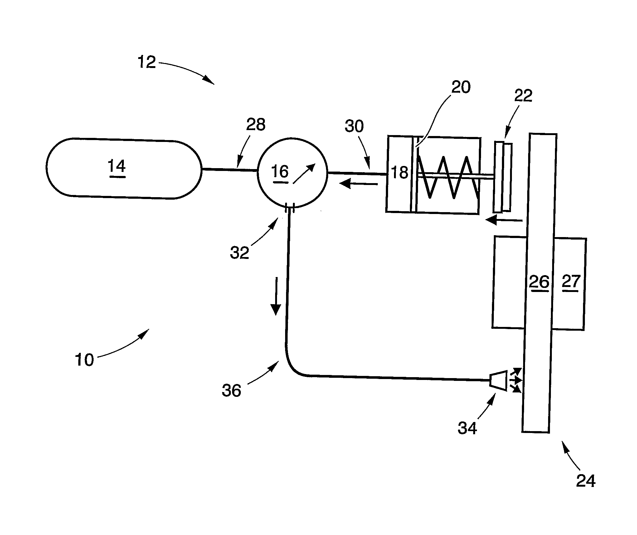
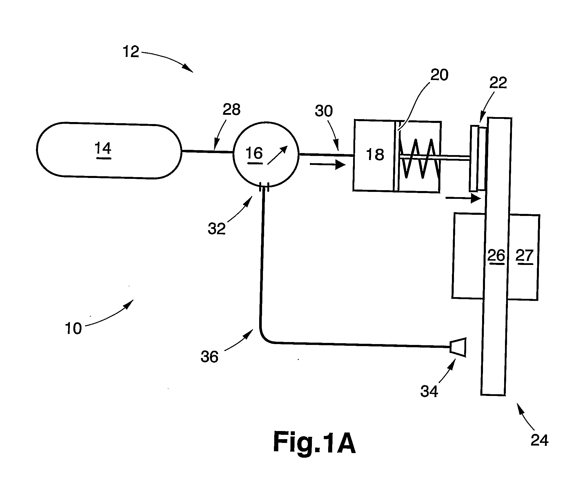
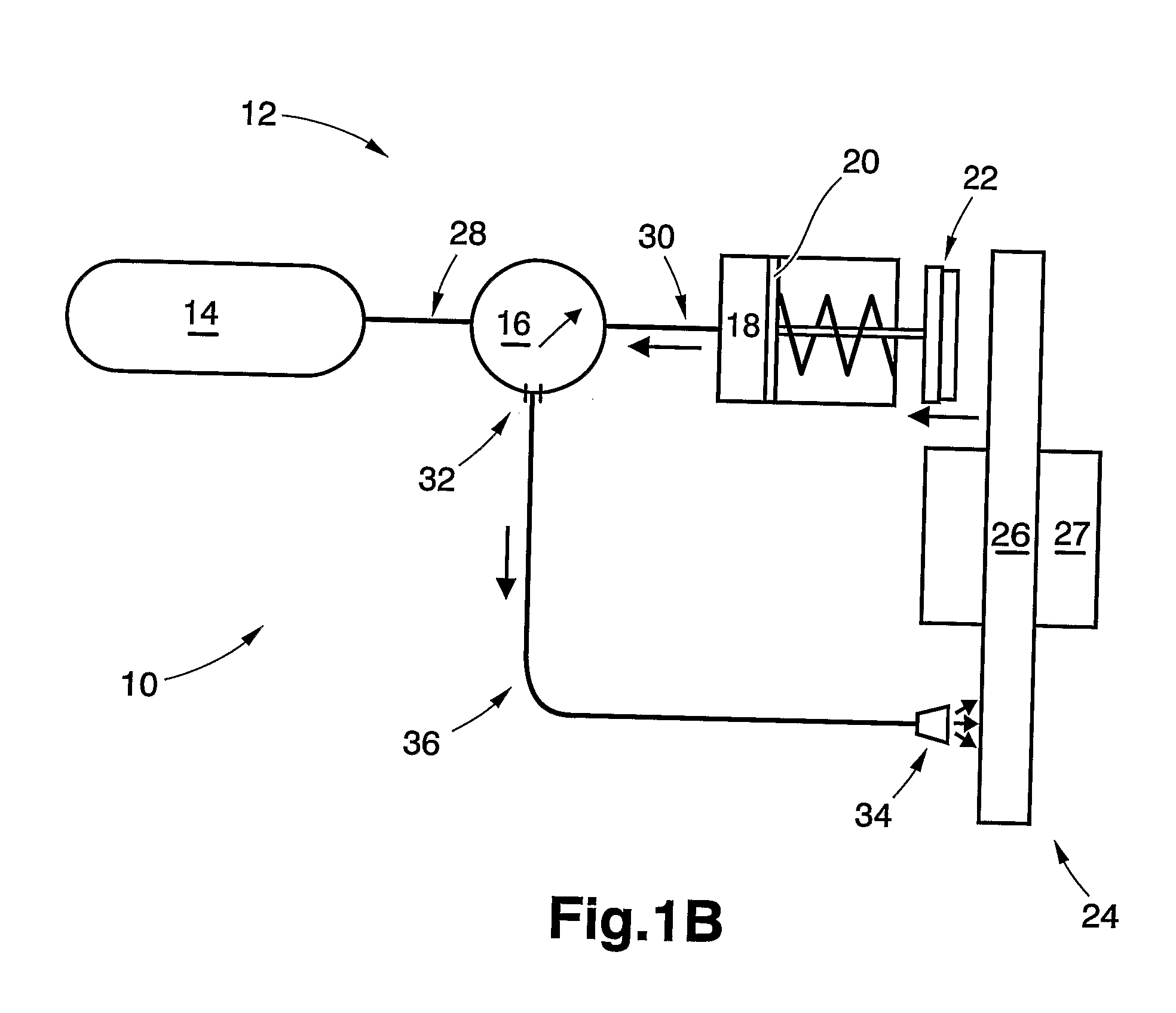
[0036]FIG. 1A illustrates a vehicle system 10 comprising a compressed air system 12. In FIG. 1A, the compressed air system 12 is a brake system but any other compressed air system 12 of the vehicle may be used in the vehicle system of the invention, as long as it provides exhaust air. Purely by way of example, a compressed air wheel suspension (not shown) may be used as the compressed air system 12 of the inventive vehicle system 10.

[0037]Irrespective of which compressed air system 12 is comprised in the vehicle system 10, the compressed air system 12 illustrated in the appended figures comprises three components: a source of compressed air 14; regulating means 16, and actuating means 18. The source of compressed air 12 is t...


PUM


Abstract

A vehicle system includes a compressed air system and a brake assembly. The compressed air system includes an actuating means for actuating a pneumatic-controlled vehicle component and an exhaust outlet adapted to discharge exhaust air from the actuating means. The vehicle system includes a discharge device for discharging air to at least a portion of the brake assembly. A method of improving the braking characteristics of a brake assembly is also provided. Furthermore, the use of exhaust air in order to improve the braking characteristics of a brake assembly is also described.

Description

BACKGROUND AND SUMMARY[0001]The present invention relates to a vehicle system comprising a compressed air system and a brake assembly. The compressed air system comprises an actuating means for actuating a pneumatic-controlled vehicle component and an exhaust outlet adapted to discharge exhaust air from the actuating means. The vehicle system comprises a discharge device for discharging air to at least a portion of the brake assembly.[0002]The present invention also relates to a method of improving the braking characteristics of a brake assembly. Furthermore, the present invention also relates to the use of exhaust air in order to improve the braking characteristics of a brake assembly.[0003]Vehicles of today are generally provided with a plurality of brake assemblies. Generally, each one of the wheels of the vehicle is provided with a brake assembly adapted to regulate the rotational resistance of the wheel. However, in some applications it suffices to provide only a few of the whe...

Claims


Application Information

Patent Timeline
IPC IPC(8): F16D65/84B60T13/26F16D55/02F16D65/32G06F19/00F16D65/28
CPCB60T5/00F16D2065/783F16D65/78B60T13/26
Inventor SABELSTROM, MATSPETERSSON, MARTIN
Owner VOLVO LASTVAGNAR AB
Why Eureka
Try Eureka