Motor and electronic device comprising the same

a technology of electronic devices and motors, applied in the direction of dynamo-electric machines, magnetic circuit shapes/forms/construction, structural associations, etc., can solve the problems not necessarily being able to increase driving force, and extended portions becoming a factor of reducing driving efficiency, so as to improve driving efficiency, increase magnetic resistance, and keep the eddy current small

Active Publication Date: 2010-10-14
PANASONIC CORP
View PDF28 Cites 8 Cited by
  • Summary
  • Abstract
  • Description
  • Claims
  • Application Information

AI Technical Summary

Benefits of technology

[0011]According to one exemplary embodiment of the present invention, a motor is provided with sheet-like plates having extended portions, one of which disposed to the outermost side has a thickness smaller than that of other sheet-like plates laminated on the other side thereof in order to achieve the same effect as making the thickness of a part of the sheet-like plates disposed to the outermost side smaller than that of the other parts. It becomes possible by virtue of this structure to keep the eddy current small, thereby improving the driving efficiency.
[0012]In other words, there is a phenomenon in which magnetic flux of a large amount enters into the laminated sheet-like plates from one side of the extended portion confronting the magnet because of its close distance to the magnet. In the motor of the present invention, on the other hand, one of the sheet-like plates on the side confronting the magnet is formed smaller in the thickness than the other sheet-like plates laminated on the other side of this plate so as to increase the magnetic resistance. This structure thus averts the magnetic flux of the magnet from concentrating into the sheet-like plate on the side close to the magnet, and rather helps the magnetic flux to spread also to the sheet-like plates on the other side. Accordingly, this structure ensures not to induce a large eddy current in the sheet-like plate on the side close to the magnet and avoids magnetic saturation. It can hence allow the magnetic flux to enter smoothly without increasing the magnetic resistance of the sheet-like plates as a whole.
[0013]According to another exemplary embodiment of the present invention, a motor is provided with sheet-like plates having extended portions, one of which disposed to the outermost side has a boundary portion of a smaller thickness between a flat portion and an extended portion than that of the flat portion in order to achieve the same effect as making the thickness of a part of the sheet-like plates disposed to the outermost side smaller than that of the other parts. It also becomes possible by virtue of this structure to keep the eddy current small, thereby improving the driving efficiency.
[0014]That is, surfaces of the plurality of extended portions formed of the laminated sheet-like plates are covered with an insulation layer. Since the insulation layer prevents magnetic flux from crossing therethrough, the magnetic flux entering from the magnet in an orthogonal direction into the sheet-like plate on the side confronting the magnet is unable to flow into the next sheet-like plate. This can cause an eddy current to increase inside the sheet-like plate on the side confronting the magnet. In the motor of the present invention, on the other hand, one of the sheet-like plates having the extended portion disposed to the outermost side is provided with the boundary portion between the flat portion and the extended portion, wherein the boundary portion has the thickness smaller than that of the flat portion so as to increase the magnetic resistance in the curved portion. In other words, the high magnetic resistance at the boundary portion between the flat portion and the extended portion produces magnetic saturation to decrease a permeability in this portion to a level equal to or less than that of the insulation layer, thereby making the magnetic flux to flow rather easily into the next sheet-like plate having the extended portion disposed to the inner side. Accordingly, the structure can reduce the eddy current inside the extended portions as a whole, and hence improve the driving efficiency from this standpoint.
[0015]According to still another exemplary embodiment of the present invention, a motor is provided with sheet-like plates having extended portions, one of which disposed to the outermost side has the extended portion of a thickness smaller than that of the flat portion in order to achieve the same effect as making the thickness of a part of the sheet-like plates disposed to the outermost side smaller than that of the other parts. It also becomes possible by virtue of this structure to keep the eddy current small, thereby improving the driving efficiency.
[0016]That is, the laminated sheet-like plates are made of steel sheets, and the surfaces of which are coated with an insulation layer used as a protective coating. Since the insulation layer prevents magnetic flux from crossing therethrough, the magnetic flux entering from the magnet in an orthogonal direction into the sheet-like plate on the side confronting the magnet is unable to flow into the next sheet-like plate disposed at the inner side. This can cause an eddy current to increase inside the sheet-like plate on the side confronting the magnet. In the motor of the present invention, on the other hand, one of the sheet-like plates having the extended portion disposed to the outermost side (i.e., closest to the magnet) is so formed that the extended portion has the thickness smaller than that of the flat portion. In other words, the sheet-like plate having the thin extended portion disposed to the outermost side can produce magnetic saturation with a small amount of magnetic flux, and decrease permeability in this portion to a level equal to or less than that of the insulation layer. This helps the magnetic flux to flow rather easily from the sheet-like plate having the extended portion disposed to the outermost side into the next sheet-like plate having the extended portion disposed to the inner side. Accordingly, this structure can reduce the eddy current inside the extended portions as a whole, and hence improve the driving efficiency from this standpoint.

Problems solved by technology

According to the studies made by the inventors of this application, however, it was found not necessarily possible to increase the driving force by simply providing the extended portions.
When the extended portions are enlarged an amount of magnetic flux from the confronting magnets also increases proportionally however, and this gives rise to a problem that a magnetic saturation can result in a magnetic path of the stator communicating the magnetic poles.
There is also another problem that the extended portions become a factor of reducing the driving efficiency due to a large eddy current loss generated therein when the extended portions have a large thickness since they receive the magnetic flux of a considerable amount in a direction orthogonal thereto from the magnets.

Method used


Image

  • Motor and electronic device comprising the same
  • Motor and electronic device comprising the same
  • Motor and electronic device comprising the same

Examples


first exemplary embodiment

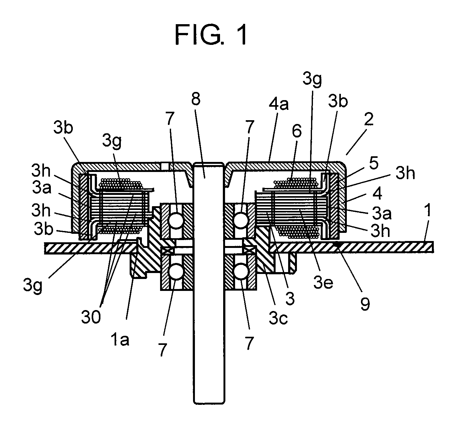
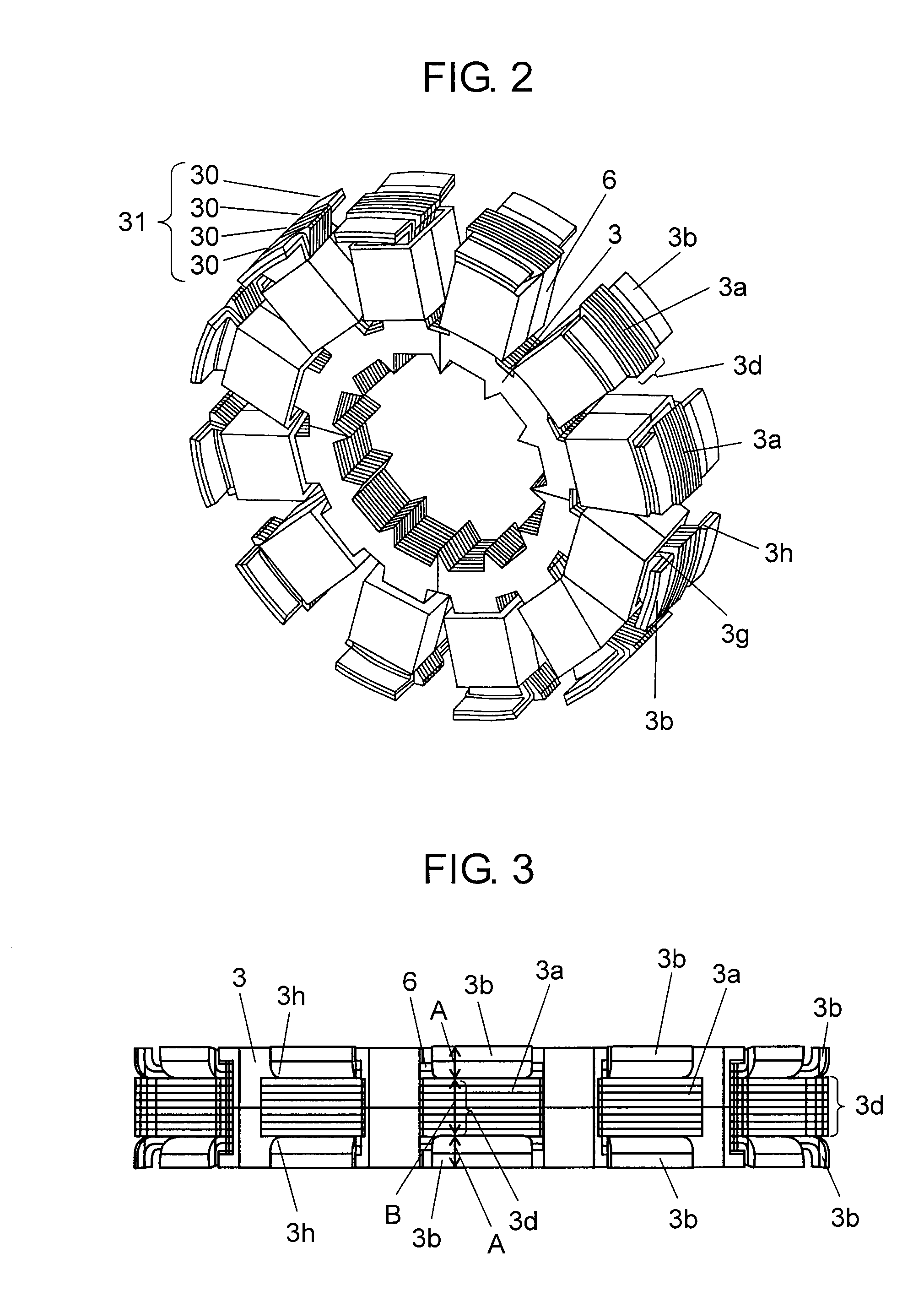
[0061]FIG. 1 is a cross sectional view showing a motor according to the first exemplary embodiment of the present invention. FIG. 2 is a perspective view showing a stator which composes the motor of the first exemplary embodiment of this invention.

[0062]As shown in FIG. 1, motor 2 is mounted on wiring board 1, which is disposed inside a main unit casing (not shown) of an electronic device (a laser printer, for instance).

[0063]Motor 2 comprises stator 3 having laminated body 31 formed by stacking sheet-like plates 30, and rotor 4 disposed in a rotatable manner around the outer periphery of stator 3 as shown in FIG. 1 and FIG. 2. Rotor 4 is cylindrical in shape with an opening in the bottom. Rotor 4 is provided with magnet5 of an annular shape fixed to an inner periphery thereof, wherein magnet 5 has N-poles and S-poles magnetized alternately (i.e., different polarities next to one another) at regular intervals determined according to a number of the poles. Stator 3 has a plurality of...

second exemplary embodiment

[0093]FIG. 8 is an enlarged side view of magnetic pole 3a of stator 3 according to the second exemplary embodiment of the present invention, and FIG. 9 is an explanatory drawing of magnetic pole 3a of stator 3 in this exemplary embodiment. A general structure of a motor of this exemplary embodiment is similar to that of the first exemplary embodiment, and details of it are therefore skipped.

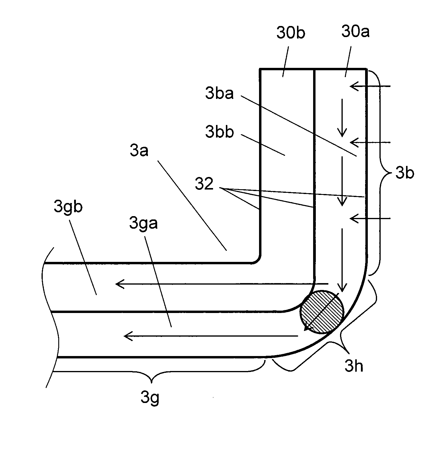
[0094]In this exemplary embodiment, a part of sheet-like plates 30 having extended portions 3b disposed to the outermost side is formed into a thickness smaller than that of the other parts. In comparison with the first exemplary embodiment, a peculiar point of this exemplary embodiment is that sheet-like plate 30 having outermost-side extended portion 3ba, or outermost-side sheet-like plate 30a, has boundary portion 3h between flat portion 3g and extended portion 3b where the thickness is reduced smaller than that of flat portion 3g. Description is now provided of a structure of magnetic poles 3...

third exemplary embodiment

[0103]FIG. 10 is an enlarged side view of sheet-like plates 30 including extended portion 3b of magnetic pole 3a according to the third exemplary embodiment of the present invention, and FIG. 11 is an explanatory drawing of sheet-like plates 30 including extended portion 3b of magnetic pole 3a according to this exemplary embodiment. Since a general structure of a motor of this third exemplary embodiment is similar to those of the first and the second exemplary embodiments, details of it are skipped.

[0104]In this exemplary embodiment, a part of sheet-like plates 30 having extended portions 3b disposed to the outermost side is also formed into a thickness smaller than that of the other parts. In comparison with the first exemplary embodiment, a peculiar point of this exemplary embodiment is that at least outermost-side extended portion 3ba of at least one of sheet-like plates 30 having extended portion 3b, i.e., outermost-side sheet-like plate 30a, has a thickness smaller than that of...


PUM


Abstract

A motor comprising a stator having a plurality of magnetic poles disposed in a circumferential direction along an outer periphery thereof, a rotor disposed rotatably around the outer periphery of the stator, and a magnet disposed in a circumferential direction along an inner periphery of the rotor. The stator is formed by laminating sheet-like plates. A plurality of the sheet-like plates including an outermost layer of this laminated body comprises a flat portion substantially perpendicular to the magnet, and an extended portion bent to a direction substantially parallel to the magnet. A part of the sheet-like plate having the extended portion disposed to the outermost side is formed into a thickness smaller than thicknesses of the other parts.

Description

TECHNICAL FIELD[0001]The present invention relates to motors and electronic devices using the motors.BACKGROUND ART[0002]An electronic device such as a laser printer has a paper feed roller (i.e., driven unit) coupled with a motor and disposed inside a main unit casing, and this motor drives the paper feed roller to rotate and deliver paper to a predetermined section.[0003]The above motor comprises a stator having a plurality of magnetic poles disposed at first predetermined intervals in a circumferential direction along an outer periphery thereof, and a rotor disposed around the outer periphery of the stator. The rotor has a structure comprising magnets disposed at second predetermined intervals in a circumferential direction along an inner periphery thereof with their poles magnetized alternately to have different polarities.[0004]The stator is also provided with an extended portion formed on each of the magnetic poles in a manner to extend from the base of the magnetic pole into ...

Claims


Application Information

Patent Timeline
Patent Type & Authority Applications(United States)
IPC IPC(8): H02K1/14
CPCH02K1/148H02K1/187H02K21/222H02K1/146H02K11/001H02K11/0021H02K1/2706H02K11/20H02K11/215
Inventor YOSHIKAWA, YUICHIMURAKAMI, HIROSHIKOSHIBA, ATSUYOSHIKATO, HARUKIKUNISHIGE, YASUOKADOWAKI, KOJIASAI, HIROYUKI
Owner PANASONIC CORP
Why Eureka
Try Eureka