Eureka AIR delivers breakthrough ideas for toughest innovation challenges, trusted by R&D personnel around the world.

Control apparatus

a control apparatus and communication network technology, applied in electrical apparatus, digital transmission, data switching networks, etc., can solve the problems of packet loss, packet loss, packet loss, etc., and achieve the effect of reducing the discard rate and lowering the transfer efficiency

Inactive Publication Date: 2010-10-14
HITACHI LTD
View PDF2 Cites 2 Cited by
  • Summary
  • Abstract
  • Description
  • Claims
  • Application Information

AI Technical Summary

Benefits of technology

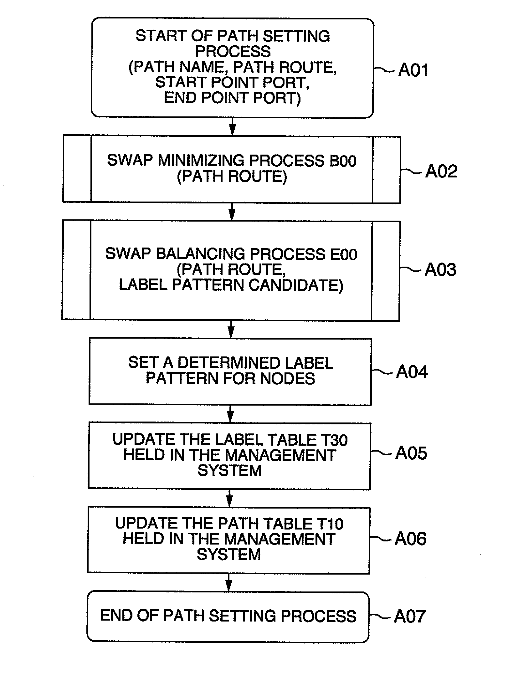
[0021]It is therefore necessary to provide a process of dispersing a label swapping process to each node while reducing the label swapping process as sufficiently as possible in order to reduce the load based on processing of the error correction code while the transfer efficiency is kept high.
[0022]The aforementioned issues can be solved by provision of a method which reduces determines a given label to reduce the number of label swaps in the whole network and disperse the number of label swaps to each node as sufficiently as possible.
[0024]It is possible to achieve a packet transport system in which packet discard rate is reduced without lowering of transfer efficiency.

Problems solved by technology

In a network using a packet transfer method, if traffic exceeding the transfer throughput capacity of each node flows in a certain node, packet loss occurs to lower transmission quality.
If traffic is concentrated in a certain node, packet loss occurs though the whole network still has a surplus throughput capacity.
On the other hand, lowering of quality due to packet loss is also caused by transmission error of link between respective nodes.
In the MPLS method in which an error correction code is not given, if there is 1-bit error in a label, correct path selection cannot be made.
Because 1-bit error causes 1-packet loss, a BER (Bit Error Rate) increases.
In any case, packet loss occurs.
If the label swap processing load per node is too large, the processing time per packet becomes long.
If the throughput capacity of each node is outstepped, packet delay and packet loss are brought.
The same issues may arise in a system using not only error correction but also a process (such as encryption) which needs to be re-executed in accordance with each label swap.
As described above, the load based on processing of the error correction code increases as the number of packets performing label swapping increases.
The MPLS method is however characterized in small overhead due to a short label, so that transfer efficiency is lowered if such a long label is used.

Method used


Image

  • Control apparatus
  • Control apparatus
  • Control apparatus

Examples


embodiment 1

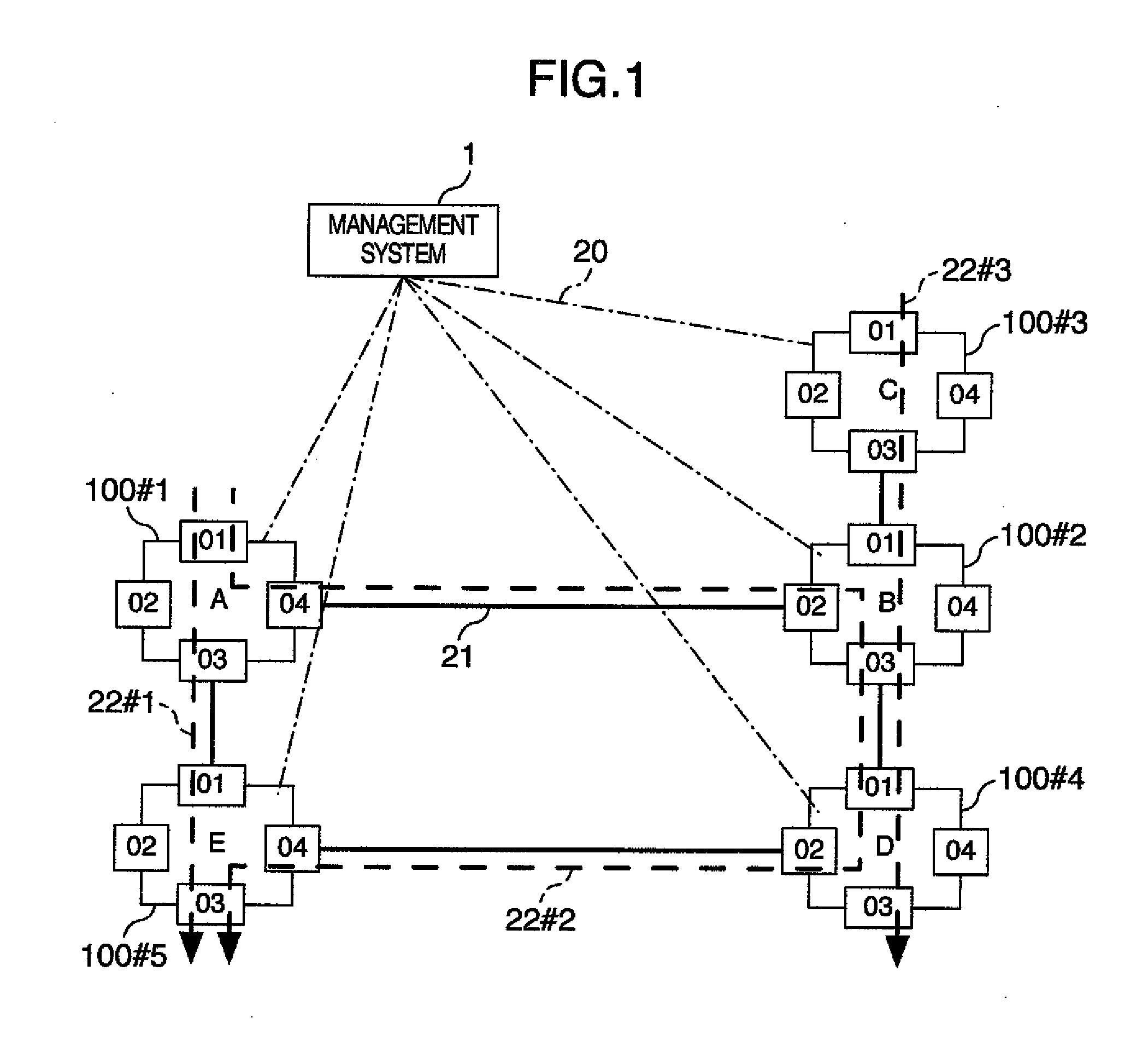
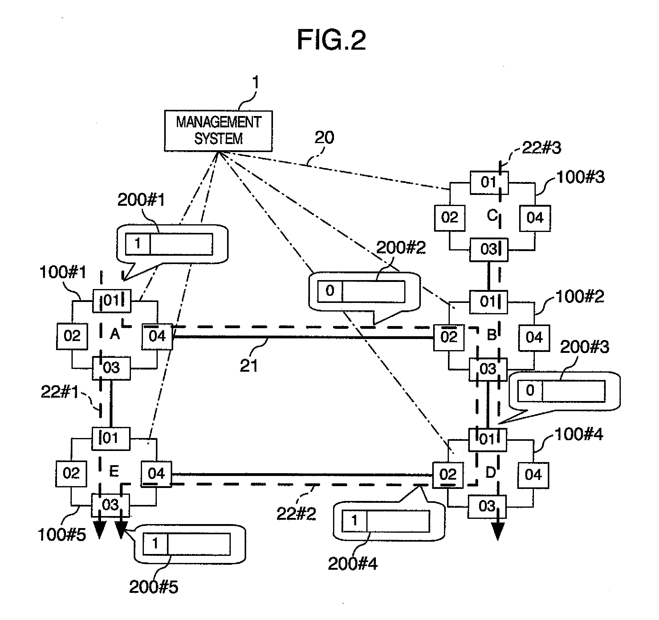
[0047]The configuration of an MPLS system will be described with reference to FIG. 1. In FIG. 1, five MPLS nodes (node devices) 100#1 to 100#5 form an MPLS network. The respective MPLS nodes 100 are connected to one another by an inter-node network 21.

[0048]The MPLS nodes 100 are logically connected to a management system 1 while MPLS nodes 100#1 and 100#4 connected by a management information transfer network 20 other than a main circuit are used as gateways. The management system 1 remotely monitors and controls the MPLS nodes 100 through the management information transfer network 20.

[0049]Connection ports of the MPLS nodes 100 to the inter-node network 21 are defined as “Side01”, “Side02”, “Side03” and “Side04”.

[0050]Although Embodiment 1 shows the case where the number of connection ports of each MPLS node to the inter-node network 21 is 4 at maximum, the upper limit of the number of connection ports is not determined for carrying out this embodiment because this embodiment can...


PUM


Abstract

An arithmetic operation portion including a swap arithmetic operation portion which performs an arithmetic operation of swap information concerned with a path route of a packet, and a label processing portion which sets adjustment of a first label based on a result of the arithmetic operation executed by the swap arithmetic operation portion is provided in a control apparatus to thereby attain compatibility between dispersion of packet transfer load and reduction of an error rate in each link.

Description

INCORPORATION BY REFERENCE[0001]The present application claims priority from Japanese application JP 2009-095531 filed on Apr. 10, 2009, the content of which is hereby incorporated by reference into this application.BACKGROUND OF THE INVENTION[0002]1. Field of the Invention[0003]The present invention relates to a control apparatus and program for monitoring a communication network. Particularly, it relates to a system for controlling an MPLS (Multi-Protocol Label Switching) network.[0004]2. Description of the Background Art[0005]Nowadays, a transmission network accommodating various client protocols has been required toward transition to a next-generation network which will perform diversified services.[0006]A method called MPLS (Multi-Protocol Label Switching) in which a frame or packet is transferred while an identifier called label is added to the frame or packet has attracted attention as a method for accommodating various client protocols.[0007]In the next-generation network, h...

Claims


Application Information

Patent Timeline
Patent Type & Authority Applications(United States)
IPC IPC(8): H04L12/56H04L45/121H04L45/42H04L45/50
CPCH04L45/50H04L45/00
Inventor KAMIYA, AKIHIRONONAKA, YASUMICHIKUSAMA, KAZUHIROKATAOKA, KENJI
Owner HITACHI LTD
Why Eureka
Eureka Blog
Learn More