Wave pump used to transform the wave energy into another type of usable energy

a wave energy and wave pump technology, applied in the field of energy transformation industry, can solve the problems of erratic behavior, difficulty in controlling, and magnitudes that can exceed any economically viable resistance, and achieve the effect of long useful li

Inactive Publication Date: 2010-10-21
POWER RETAILING GROUP DE C V
View PDF11 Cites 0 Cited by
  • Summary
  • Abstract
  • Description
  • Claims
  • Application Information

AI Technical Summary

Benefits of technology

[0014]The principal object of the present invention is to make possible an efficient mechanism of extraction of the sea waves energy, with qualities of long useful life.
[0016]Still another object is to achieve in this mechanism the possibility of transforming the sea waves energy into an energy that can be controlled in its application.

Problems solved by technology

One of the problems of this type of energy, that is, of the alternative energies, is the difficulty to control them, their erratic behavior, appearing in a very high level at some moments and at others in a non-existent way.
Besides the energy magnitude, this is manifested with variable direction vectors, erratic frequency, and it is chemically aggressive (corrosion), and it appears with magnitudes that can exceed any economically viable resistance.
This mechanism presents several disadvantages, one of them, for example, is that the energy obtained from the waves has to be used immediately, otherwise this energy is lost, because it can not be stored.
Another example of disadvantage is that this energy is proportional to the energy contained in the wave at any given time and it is not possible to control said energy.
This mechanism has as principial disadvantage to need to be anchored firmly at the bottom of the marine bed, which means high installation costs and with the sea behavior, a very short useful life.

Method used


Image

  • Wave pump used to transform the wave energy into another type of usable energy
  • Wave pump used to transform the wave energy into another type of usable energy
  • Wave pump used to transform the wave energy into another type of usable energy

Examples


Embodiment Construction

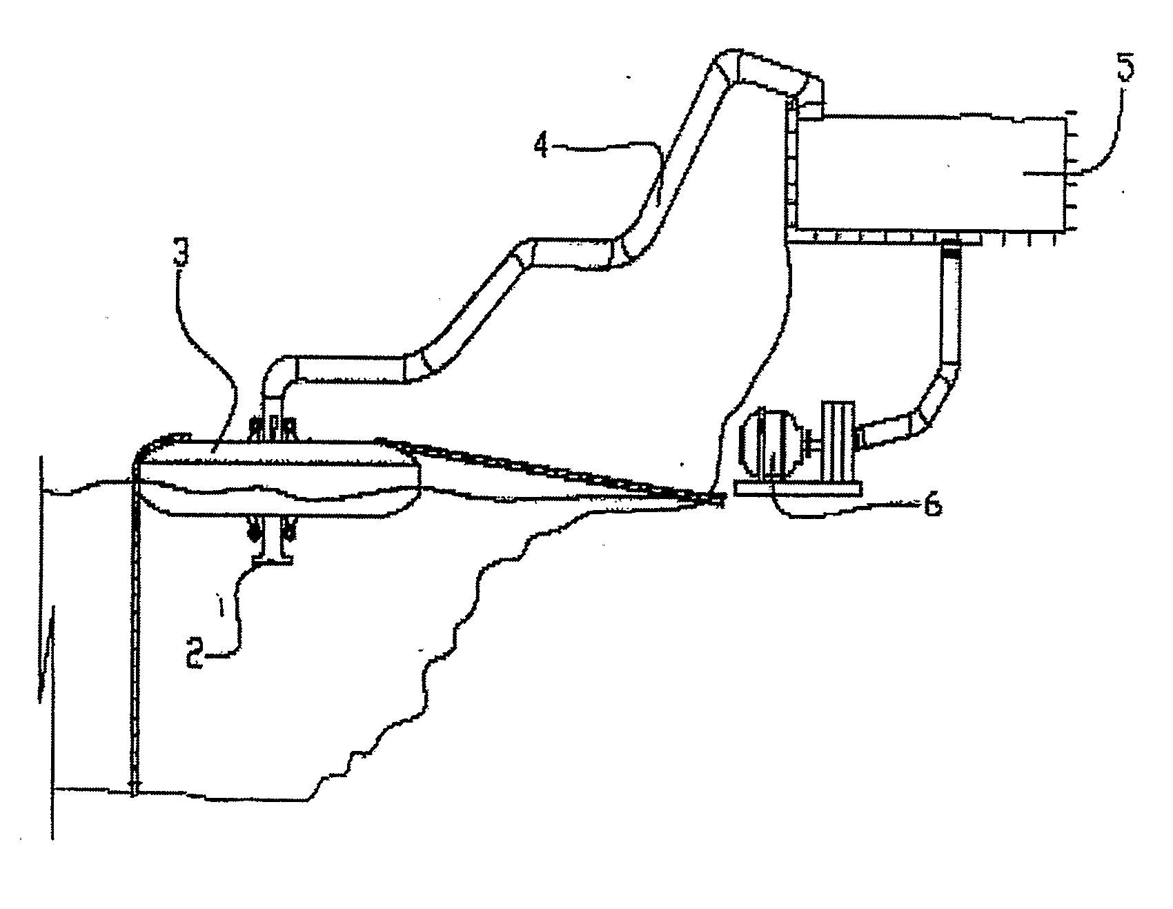
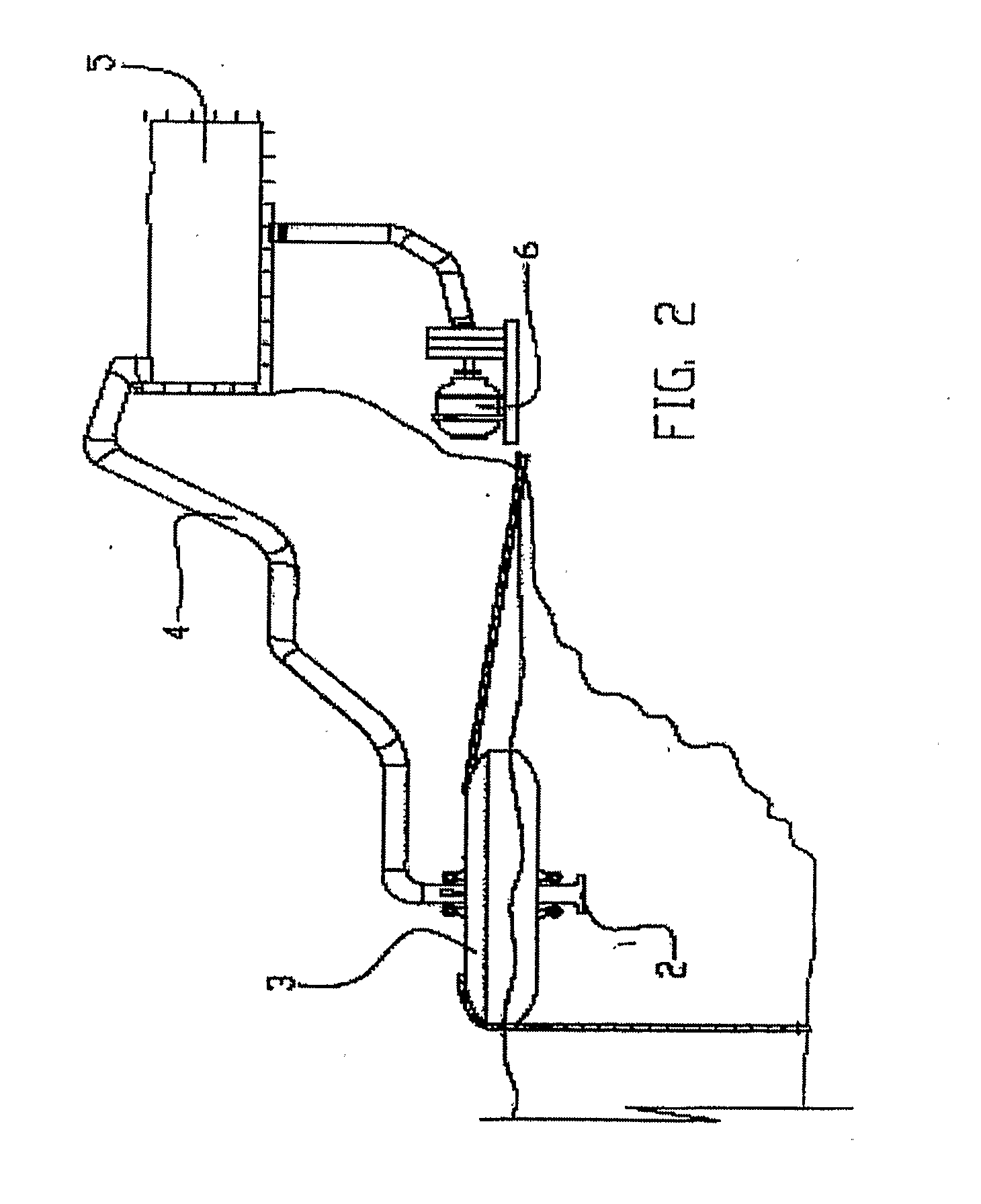
[0033]The characteristic details of this new equipment to extract sea waves energy will be shown with the detailed description of the embodiment illustrated in the attached drawings, indicating the same parts with the same reference signs to indicate the same.

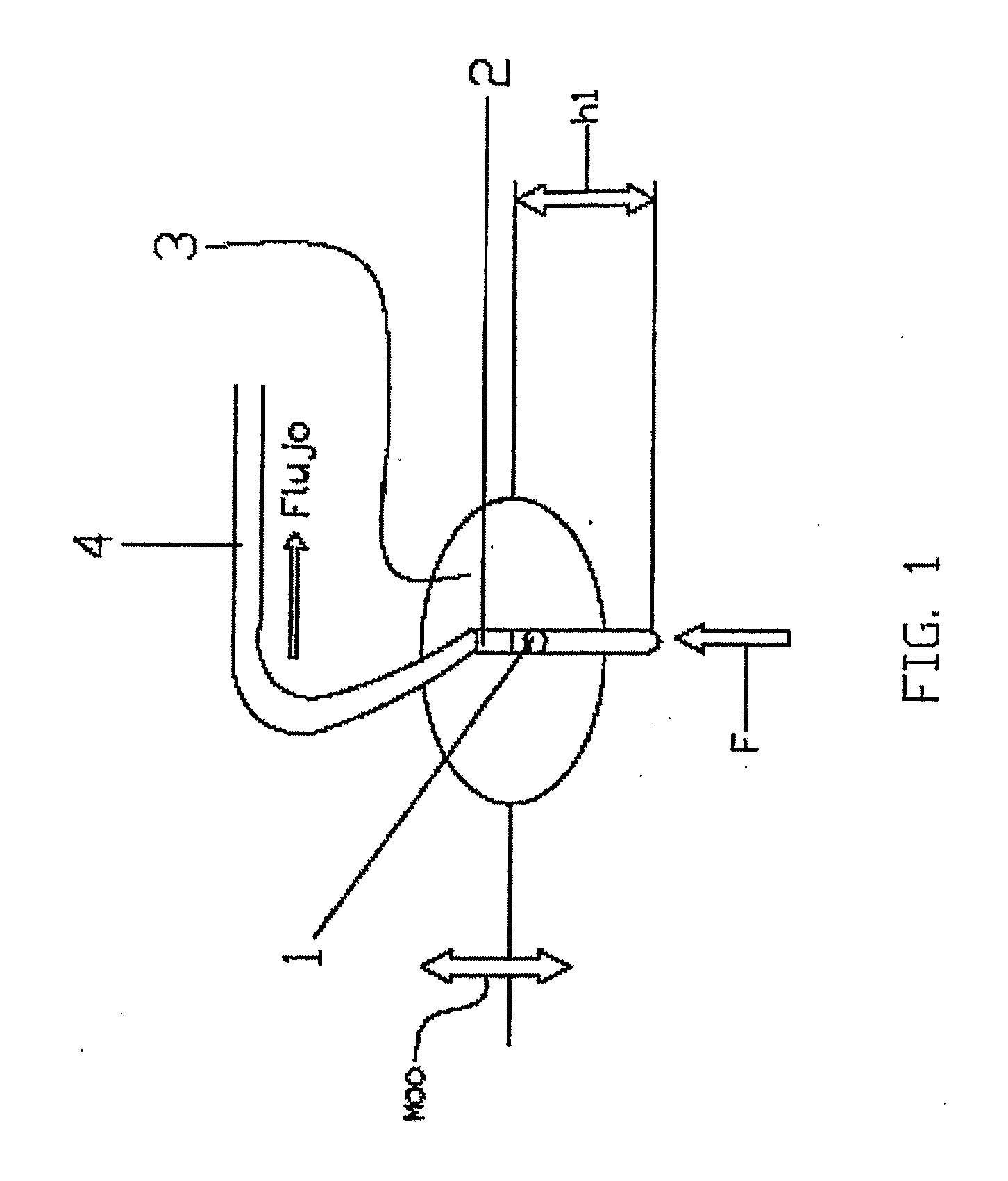
[0034]FIG. 1 shows a schematic illustration of an equipment part for the energy extraction of the sea waves, for explaining the pumping mechanism.

[0035]When the wave acts over the buoy 1 causes vertical displacements* MOO (upwards and downwards of which limit is the height h1 of the acting wave), so that when this one is rising from the trough, with the wave up to the crest, water particle displacements are induced downwards causing a pressure difference (gradient) or vacuum in the rigid pipe 2 (in the space occupied by the water level and the check valve 3) and by continuing this way with this cyclical wave movement departing now from the crest (downwards buoy), the displacement senses or particle speeds are inverted until arr...


PUM


Abstract

The present invention relates to the energy transformation industry, and more specifically to the device manufacturing industry for the transformation of natural alternative energies into more controllable and relatively easy to store energy. The advantages of the present equipment with respect of those of the prior art relies on that the present is of long useful life, which can extract from the waves energy that can be stored to be used at the time it is needed and with the capacity of being controlled in its application. Structurally the equipment of the present invention is characterized by comprising a float having an orifice in the center, in this orifice it is disposed firmly fastened a rigid pipe hydraulically connected at one of its ends to a hose, and at the other end to a check valve in the end immersed in the water bed; the opposite end of the hose which is hydraulically joined to the rigid pipe, the hose ends in a water tank on dry land and above the sea level average.

Description

FIELD OF THE INVENTION[0001]The present invention relates to the energy transformation industry, and more specifically to the of non-pollutant device manufacturing industry for the transformation of natural alternative energies into more controllable and relatively easy to store energy.BACKGROUND OF THE INVENTION[0002]It is undeniable, with certain doubts over the nuclear energy, that the conjunt of energy sources in the planet Earth, directly or indirectly, comes from the solar energy. If we think about the eolic energy, for example, this is due to the convection air currents due to the temperature gradients formed by the different form in which the sun warms different points in the planet.[0003]One of the problems of this type of energy, that is, of the alternative energies, is the difficulty to control them, their erratic behavior, appearing in a very high level at some moments and at others in a non-existent way.[0004]One of the energy sources that is erratic, but only in its ma...

Claims


Application Information

Patent Timeline
Patent Type & Authority Applications(United States)
IPC IPC(8): F03B13/18
CPCF03B13/145Y02E10/38F03B13/1815F03B13/147Y02E10/30
Inventor REGO GARCIA DE ALBA, LUIS FELIPE
Owner POWER RETAILING GROUP DE C V
Why Eureka
Try Eureka