
Apparatus for fixing plastic sheet and method of fabricating NANO pattern on plastic sheet using the same

a technology of plastic sheet and nano pattern, which is applied in the direction of electric/magnetic/electromagnetic heating, instruments, applications, etc., can solve the problems that nano pattern cannot be formed on a substrate having a thickness less than a predetermined level, surface roughness of 10 micrometers or less does not ensure the formation of nano pattern stably and repeatedly, etc., to achieve easy attachment to a desired substrate, enhance radiation efficiency, and reduce roughness

Inactive Publication Date: 2010-10-21
ELECTRONICS & TELECOMM RES INST
View PDF6 Cites 4 Cited by
  • Summary
  • Abstract
  • Description
  • Claims
  • Application Information

AI Technical Summary

Benefits of technology

[0021]According to the present embodiment, a nano pattern can be fabricated on a plastic sheet having less roughness than that of a semiconductor substrate or a glass substrate. Also, the plastic sheet having the nano pattern thereon can be easily attached to a desired substrate using plasma treatment or adhesive. Thus, the plastic sheet can be attached to a diagnosis kit for a bio-plastic diagnosis kit or an exterior packaging material of an optical device, for example, an outer portion of a window of a packaging can of the optical device or an outer portion of a dome-shaped plastic of a light emitting device. This enhances radiation efficiency with low production costs.

Problems solved by technology

Therefore, this technology does not allow use of a plastic sheet made of e.g., polymer having a thickness of 1000 micro meter or less.
Accordingly, a problem with the imprinting is that the nano pattern cannot be formed on a substrate having a thickness less than a predetermined level.
For example, in a case where Imprio series of MII corp., is employed, a substrate having a surface roughness of 10 micrometer or less does not ensure a nano pattern to be formed stably and repeatedly.
A process of forming the nano pattern on the plastic substrate by metal mold injection as described above is not cost-efficient due to considerably high manufacturing costs of a metal mold.
Besides, the molding process involves a heating process to require expensive molding equipment, thereby increasing manufacturing and maintenance costs.

Method used


Image

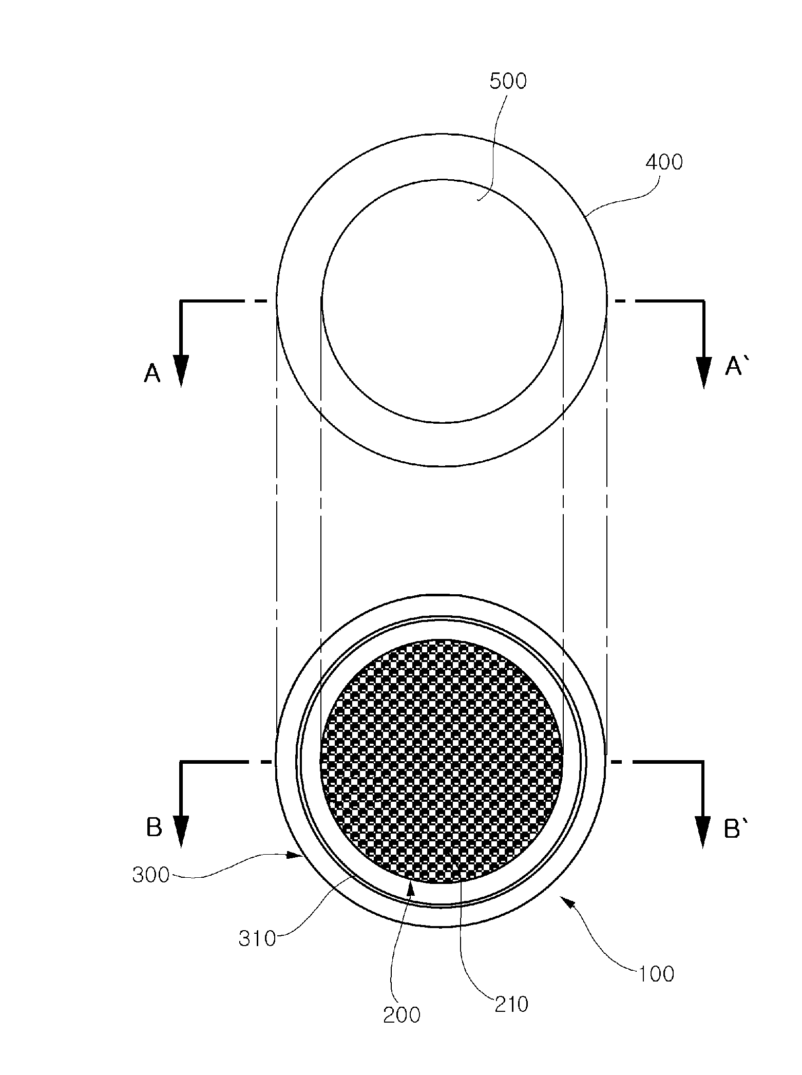
  • Apparatus for fixing plastic sheet and method of fabricating NANO pattern on plastic sheet using the same
  • Apparatus for fixing plastic sheet and method of fabricating NANO pattern on plastic sheet using the same
  • Apparatus for fixing plastic sheet and method of fabricating NANO pattern on plastic sheet using the same

Examples


Embodiment Construction

[0026]Embodiments of the present invention will now be described in detail with reference to the accompanying drawings. In the following description, well-known functions and constructions are not described in detail since they would obscure the intention in unnecessary detail. Also, the same reference signs are used to designate the same or similar components throughout.

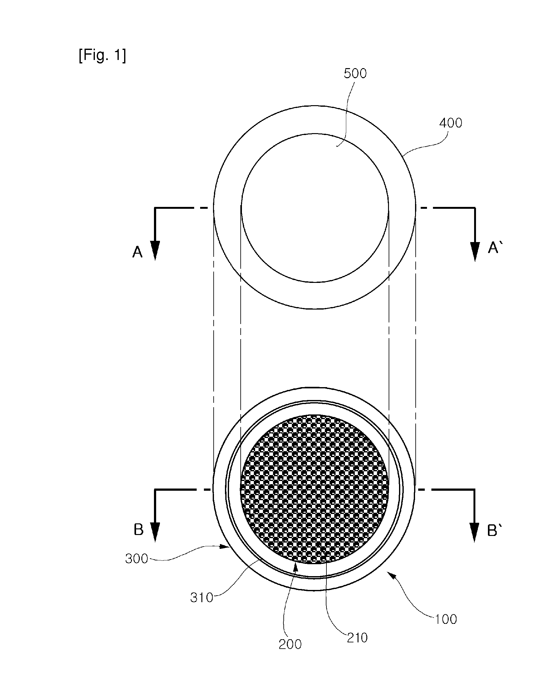
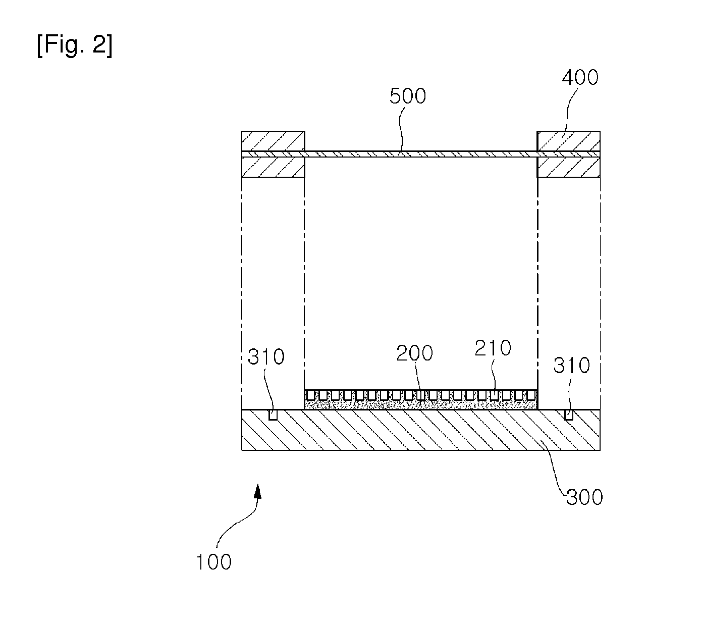
[0027]FIG. 1 illustrates an apparatus for fixing a plastic sheet according to an exemplary embodiment of the invention. In the present embodiment, the plastic sheet is illustrated as a plastic sheet 500.

[0028]Referring to FIG. 1, the apparatus for fixing a plastic sheet includes a pair of planar metal guide rings 400, and a sheet fixing chuck 100. The sheet fixing chuck 100 includes a sheet fixer 200, and a ring fixer 300 having the pair of planar metal guide rings 400 fixed thereto.

[0029]The sheet fixing chuck 100 is made of aluminum or stainless steel. The sheet fixer 200 is provided in a central portion thereof w...


PUM

PropertyMeasurementUnit
surface roughnessaaaaaaaaaa
thicknessaaaaaaaaaa
thicknessaaaaaaaaaa

Abstract

There are provided an apparatus for fixing a plastic sheet which fixes a plastic sheet to fabricate a nano pattern and a method of fabricating a nano pattern on a plastic sheet using the same. The apparatus for fixing a plastic sheet includes: a pair of planar metal guide rings interposingly fixing a plastic sheet from above and below, respectively; and a sheet fixing chuck including: a ring fixer sucking the pair of planar metal guide rings through a vacuum groove to be fixed thereto; and a sheet fixer having a plurality of vacuum pin holes formed therein, the vacuum pin holes sucking a bottom of the plastic sheet fixed by the planar metal guide rings. The apparatus allows fabrication of the nano pattern on the plastic sheet having less roughness than that of a semiconductor substrate or a glass substrate.

Description

TECHNICAL FIELD[0001]The present invention relates to a fabrication method of a nano pattern and an application technology thereof, and more particularly, to an apparatus for fixing a plastic sheet which fixes a plastic sheet to fabricate a nano pattern and a method of fabricating a nano pattern using the same.[0002]The work related to the present invention was supported by the IT R&D program of MIC / IITA [Project No. 2006-S-007-02, project title: Ubiquitous Health Monitoring Module and System Development].BACKGROUND ART[0003]There are largely two technologies for fabricating a nano pattern on a substrate. One is electronic beam lithography in which lithography is performed using an electronic beam, followed by etching. The other is imprinting in which a nano pattern is transferred onto a substrate using a stamp.[0004]In the electronic beam lithography, mainly, a nanometer pattern is formed on an electronic resist (ER) and then etched to fabricate a final pattern. Meanwhile, in the i...

Claims


Application Information

Patent Timeline
Patent Type & Authority Applications(United States)
IPC IPC(8): B29C59/16
CPCB82Y10/00H01L21/6838G03F7/0002B82Y40/00H01L21/687
Inventor KIM, KYUNG HYUNHUH, CHULKO, HYUN SUNGHONG, JONG CHEOLKIM, WAN JOONGSUNG, GUN YONGPARK, SEON HEE
Owner ELECTRONICS & TELECOMM RES INST
Learn More