Permanent-magnet synchronous machine with suppression means for improving the torque ripple

a technology of permanent magnet and torque ripple, which is applied in the direction of dynamo-electric machines, magnetic circuit rotating parts, magnetic circuit shape/form/construction, etc., can solve the problems of torque ripple and oscillation torque, and achieve the effect of simplifying manufacturing

Inactive Publication Date: 2010-10-21
SIEMENS AG
View PDF6 Cites 28 Cited by
  • Summary
  • Abstract
  • Description
  • Claims
  • Application Information

AI Technical Summary

Benefits of technology

[0011]In addition, a double skew with a first and a second skew angle is possible, in which the second suppression means are in the form of a first skew, and the third suppression means are in the form of a second skew. This results in similar advantages to in the case of the double staggering, it being possible for a double skew to be provided both on the rotor and on the stator.
[0012]In a further configuration, some of the suppression means can be provided on the stator and some on the rotor. In particular, the second suppression means are provided as the first skew of the slots, and the third suppression means are provided as the second skew or staggering of the permanent magnets. Owing to the measures being split up in this way, simpler manufacture can be achieved, in particular if the physical conditions are tight.

Problems solved by technology

This component brings about cogging and results in oscillating torques.
Interactions between the rotor and stator magnetic field waves are further causes of the torque ripple.

Method used


Image

  • Permanent-magnet synchronous machine with suppression means for improving the torque ripple
  • Permanent-magnet synchronous machine with suppression means for improving the torque ripple
  • Permanent-magnet synchronous machine with suppression means for improving the torque ripple

Examples


Embodiment Construction

[0025]Mutually corresponding parts are provided with the same reference symbols in FIGS. 1 to 9.

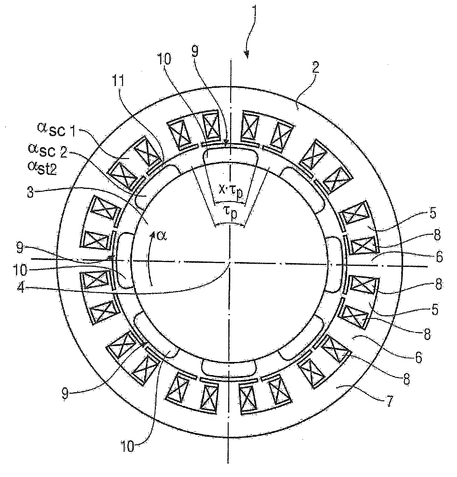
[0026]FIG. 1 shows a permanent-magnet synchronous machine 1 in the form of a motor, in a cross-sectional illustration. It contains a stator 2 and a rotor 3, which is mounted such that it can rotate about an axis of rotation 4. The rotor 3 is an internal rotor, or, as shown in FIG. 9, an external rotor. The stator 2 contains a plurality of (in the exemplary embodiment in FIG. 1 in total twelve) slots 5, which are distributed uniformly over the circumference and between which in each case teeth 6 are formed, on its inner wall facing the rotor 3. An outwardly circumferential yoke 7 connects the teeth 6 to one another. Tooth-wound coils 8, which each surround a tooth 6, are arranged in the slots 5. The rotor 3 is provided with permanent magnets 9, which are arranged such that in total eight magnet poles 10 result which are distributed uniformly over the circumference. In this case, a pole pit...


PUM


Abstract

A permanent-magnet synchronous machine for suppressing harmonics includes a stator and a rotor with permanent magnets. Each permanent magnet represents a magnetic pole and is, when viewed in the circumferential direction of the rotor, shaped as a parallelogram or an arrow. The pole coverage is less than one. The permanent magnets are staggered at a staggering angle, wherein the permanent magnets of one pole are arranged in the axial direction with an increasing offset of a circumferential angle in relation to a first permanent magnet of this pole. Each permanent magnet is skewed at a skew angle defined by a circumferential angle of a projection of a tip portion of the parallelogram or arrow. The optimal skew and staggering angles are calculated from the design parameters for the stator and the number of pole pairs and the number of poles in the axial direction of the rotor.

Description

CROSS-REFERENCES TO RELATED APPLICATIONS[0001]This application is a continuation of prior filed copending U.S. application Ser. No. 11 / 575,718, filed Mar. 21, 2007, which is a U.S.-National Stage of International Application No. PCT / EP2005 / 054622, filed Sep. 16, 2005, which claims the priority of German Patent Application, Serial No. 10 2004 045 939.8, filed Sep. 22, 2004, the content of which are incorporated herein by reference in its entirety as if fully set forth herein.BACKGROUND OF THE INVENTION[0002]The invention relates to a permanent-magnet synchronous machine with a stator provided with slots and with a rotor provided with permanent magnets, which form magnetic poles.[0003]Such a permanent-magnet synchronous machine often has a certain degree of torque ripple during operation. In order to reduce this torque ripple, various suppression means are known. For example, DE 100 41 329 A1 discloses that a pole coverage of the surface of the rotor with permanent magnets of from 70 ...

Claims


Application Information

Patent Timeline
Patent Type & Authority Applications(United States)
IPC IPC(8): H02K1/27
CPCH02K1/278H02K29/03H02K21/12
Inventor BRAUN, MATTHIASSCHUNK, HOLGERVOLLMER, ROLF
Owner SIEMENS AG
Why Eureka
Try Eureka