Detection of magnetic resonance signals using a magnetoresistive sensor

Active Publication Date: 2010-10-21
RGT UNIV OF CALIFORNIA
View PDF5 Cites 17 Cited by
  • Summary
  • Abstract
  • Description
  • Claims
  • Application Information

AI Technical Summary

Benefits of technology

[0008]By way of this invention, it has been found that solid state magnetoresistive sensors, including anisotropic magnetoresistive (AMR) sensors, giant magnetoresistive (GMR) anisotropic magnetoresistive sensors, and magnetic tunnel junction (MTJ) sensors can afford the high sensitivities needed for use with NMR remote detection modalities to profile microfluidic flow and assay very small amounts of a substance. As used herein, microfluidic flow is used to denote capillary

Problems solved by technology

These techniques, however, by their very nature result in a degree of sample contamination due to the addition of the marker.
Moreover, optical methods may not be applicable for chips or where the fluidic sample is optically opaque.
Another drawback of these techniques is their lack of specificity, where on

Method used


Image

  • Detection of magnetic resonance signals using a magnetoresistive sensor
  • Detection of magnetic resonance signals using a magnetoresistive sensor
  • Detection of magnetic resonance signals using a magnetoresistive sensor

Examples


Embodiment Construction

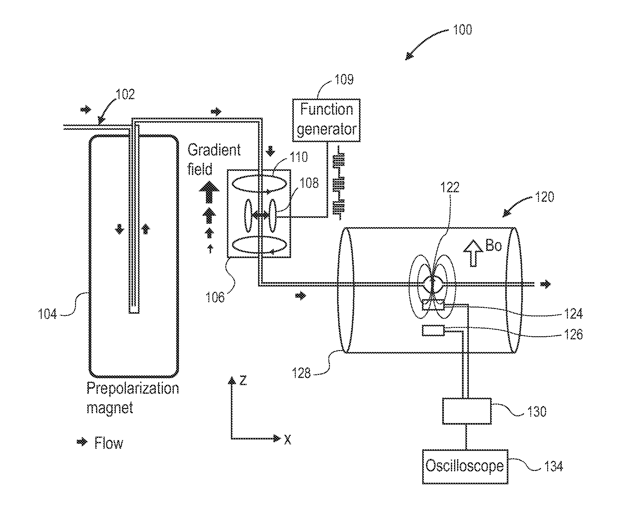
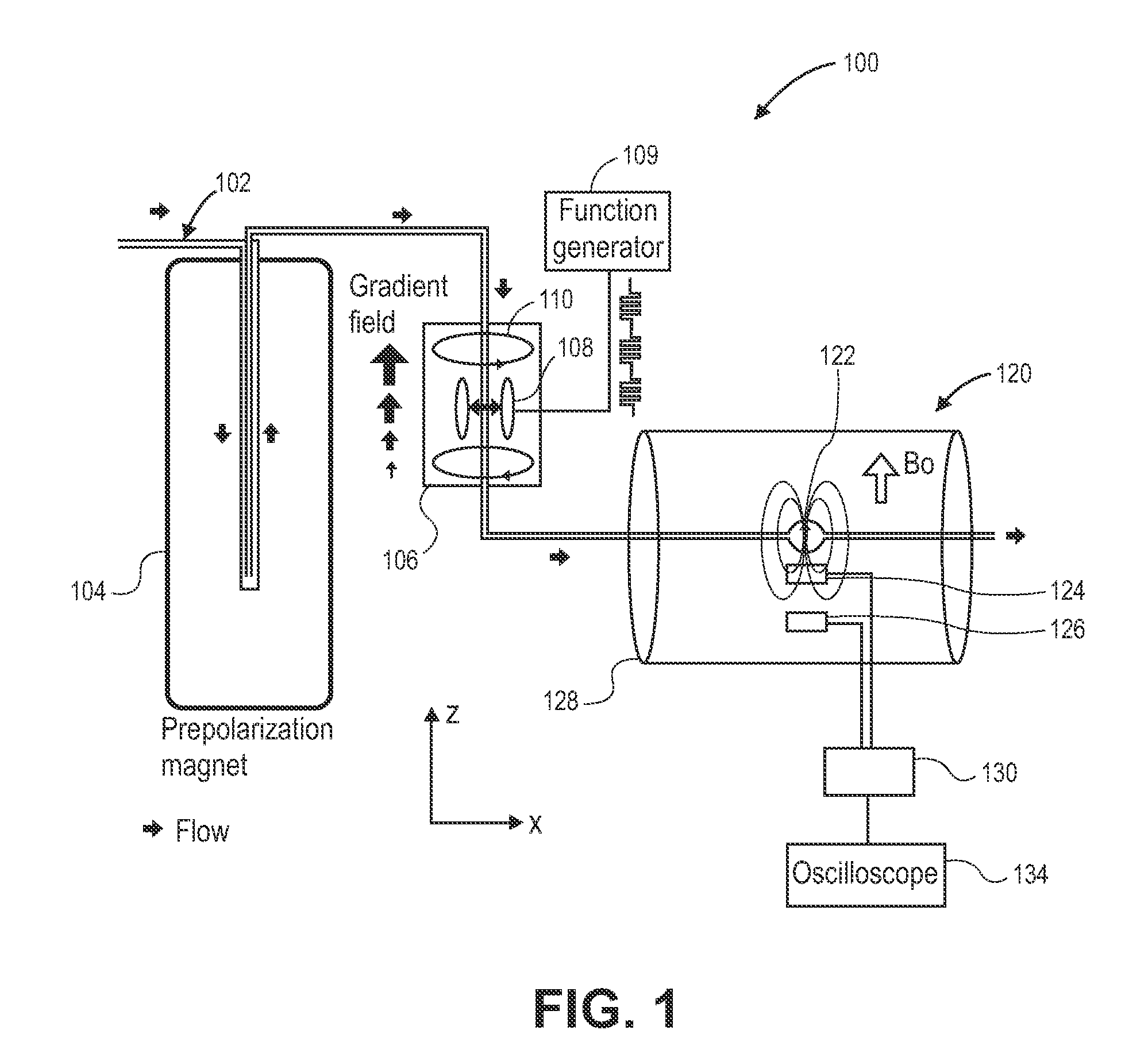
[0018]The methods and apparatus of this invention use solid-state magnetoresistive sensors to detect changes in the magnetic field of a material after is has been magnetized. By using such solid-state detectors, one can obtain accurate fluidic measurements for very small amounts of fluids in the micro sample (nanoliter) range without contamination of the sample. In this context it has been found that the use of magnetoresistive sensors, including both anisotropic magnetoresistive (AMR) sensors, especially those that rely upon the giant magnetoresistive (GMR) effect, and magnetic tunnel junction (MTJ) sensors, though compact and relatively cheap, have sufficient sensitivity to be useful in the detection of small changes in the magnetic field of these small samples.

[0019]As used herein, the term magnetoresistance is the property of a material to change the value of its electrical resistance in the presence of an external magnetic field. The term anisotropic magnetoresistance (AMR) is ...


PUM


Abstract

A method and apparatus are described wherein a micro sample of a fluidic material may be assayed without sample contamination using NMR techniques, in combination with magnetoresistive sensors. The fluidic material to be assayed is first subject to pre-polarization, in one embodiment, by passage through a magnetic field. The magnetization of the fluidic material is then subject to an encoding process, in one embodiment an rf-induced inversion by passage through an adiabatic fast-passage module. Thereafter, the changes in magnetization are detected by a pair of solid-state magnetoresistive sensors arranged in gradiometer mode. Miniaturization is afforded by the close spacing of the various modules.

Description

CROSS REFERENCE TO RELATED APPLICATIONS[0001]This utility patent application is a continuation in part of and claims the benefit of priority to International PCT Application PCT / US2008 / 078820, filed Oct. 3, 2008, which in turn claims priority to our earlier filed U.S. Provisional Application Ser. No. 60 / 977,698, filed Oct. 5, 2007, both of which applications are hereby incorporated by reference as if fully set forth in their entirety.STATEMENT OF GOVERNMENTAL SUPPORT[0002]The invention described and claimed herein was made in part utilizing funds supplied by the U.S. Department of Energy under Contracts No. DE-AC03-76SF00098, and DE-AC02-05CH11231 with the Regents of the University of California for the management and operation of the Lawrence Berkeley National Laboratory. The government has certain rights in this invention.BACKGROUND OF THE INVENTION[0003]1. Field of the Invention[0004]This invention relates generally to the assay of microliter amounts of a fluidic sample using mag...

Claims


Application Information

Patent Timeline
IPC IPC(8): G01R33/44G01R33/02
CPCB82Y25/00G01N24/08G01R33/093G01R33/302G01R33/307E03F3/046G01R33/36G01R33/44G01R33/50G01R33/5602G01R33/56375G01R33/323
Inventor BUDKER, DMITRYPINES, ALEXANDERXU, SHOUJUNHILTY, CHRISTIANLEDBETTER, MICAH P.BOUCHARD, LOUIS S.
Owner RGT UNIV OF CALIFORNIA
Why Eureka
Try Eureka