
Control system and method for reducing directional error of antenna with biaxial gimbal structure

a control system and antenna technology, applied in direction finders, instruments, antennas, etc., can solve the problems of large pointing error, inability to track when complex rocking occurs, and complex structure of four-axis mechanisms, so as to achieve the effect of reducing the pointing error of the antenna

Inactive Publication Date: 2010-10-21
FURUNO ELECTRIC CO LTD
View PDF9 Cites 19 Cited by
  • Summary
  • Abstract
  • Description
  • Claims
  • Application Information

AI Technical Summary

Benefits of technology

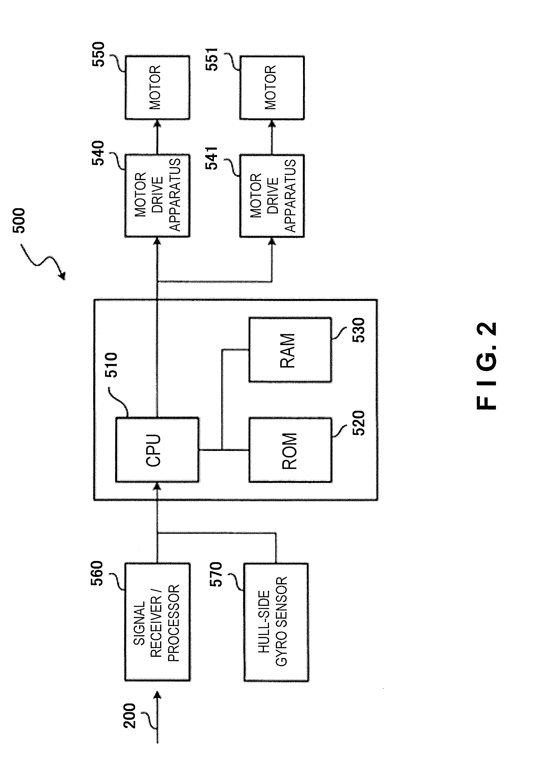
[0013]An object of the present invention is to provide an antenna pointing control apparatus and method that reduce a pointing error of an antenna having a two-axis gimbal structure using simple constituent features and a simple control.
[0017]In this case, the pointing error of the antenna can be reduced by using a simple two-axis configuration and a simple control. More specifically, even in a situation where a gimbal lock phenomenon would occur, the control instructions with respect to the azimuth axis are divided by control instructions with respect to the virtual cross elevation axis due to execution of the virtual three-axis control. As a result, the control instructions to point the antenna toward the satellite are divided, and the azimuth axis can be prevented from repeatedly rotating 180 degrees at an unrestricted speed.
[0021]In this case, the pointing error of the antenna can be reduced by using a simple two-axis configuration and a simple control. Additionally, even in a situation where gimbal lock phenomenon would occur, the control instructions with respect to the azimuth axis are divided by control instructions with respect to the virtual cross elevation axis due to execution of the virtual three-axis control. As a result, the control instructions to point the antenna toward the satellite are divided, and the azimuth axis can be prevented from repeatedly rotating 180 degrees at an unrestricted speed.

Problems solved by technology

While such a two-axis mechanism enables a simple antenna mechanism to be achieved, it is generally not capable of tracking when complex rocking occurs.
In particular, when the satellite is on the AZ axis, the pointing error becomes extremely large.
Among conventional antenna pointing apparatuses having two-axis, three-axis, and four-axis mechanisms, those having three-axis mechanisms and those having four-axis mechanisms are more complex structurally, have a higher parts cost, and cannot be made smaller in size.
Consequently, it is not possible to satisfy the rocking standard generally required for a satellite communication ship earth station (e.g., an antenna pointing error of ±5 degrees at a pitch angle of 10 degrees and a roll angle of 30 degrees).
In other words, the fixing causes the antenna pointing error to be ±10 degrees such that the pointing error does not satisfy the standard when severe rocking occurs.
H07-154127, it is difficult to accurately recognize rocking of the hull because the elevation gyroscope and the azimuth gyroscope are attached to the antenna.
H07-154128, the computations take a large amount of time, and a large cost of processing is required because a directional angle (or an estimated directional angle) of the satellite is calculated based on an estimated rocking of the hull, and an output of the apparatus is determined based on an amount of difference between the calculated value and the rotation angle about the AZ axis.
The error detecting means detects the pointing error of the directional antenna with respect to the satellite.

Method used


Image

  • Control system and method for reducing directional error of antenna with biaxial gimbal structure
  • Control system and method for reducing directional error of antenna with biaxial gimbal structure
  • Control system and method for reducing directional error of antenna with biaxial gimbal structure

Examples


Embodiment Construction

[0036]An embodiment of the present invention will now be explained. This embodiment relates to a case in which an antenna is pointed at a satellite using an antenna pointing control apparatus and an antenna pointing control method. However, the target need not be a satellite and the present invention can be applied to any other signal transmission source, such as a ship hull or a lighthouse.

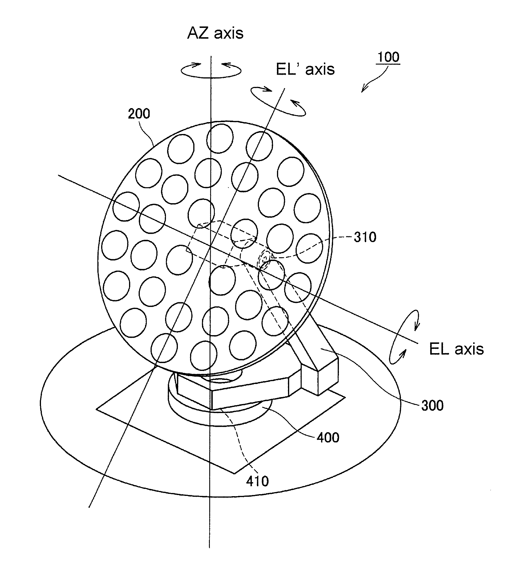
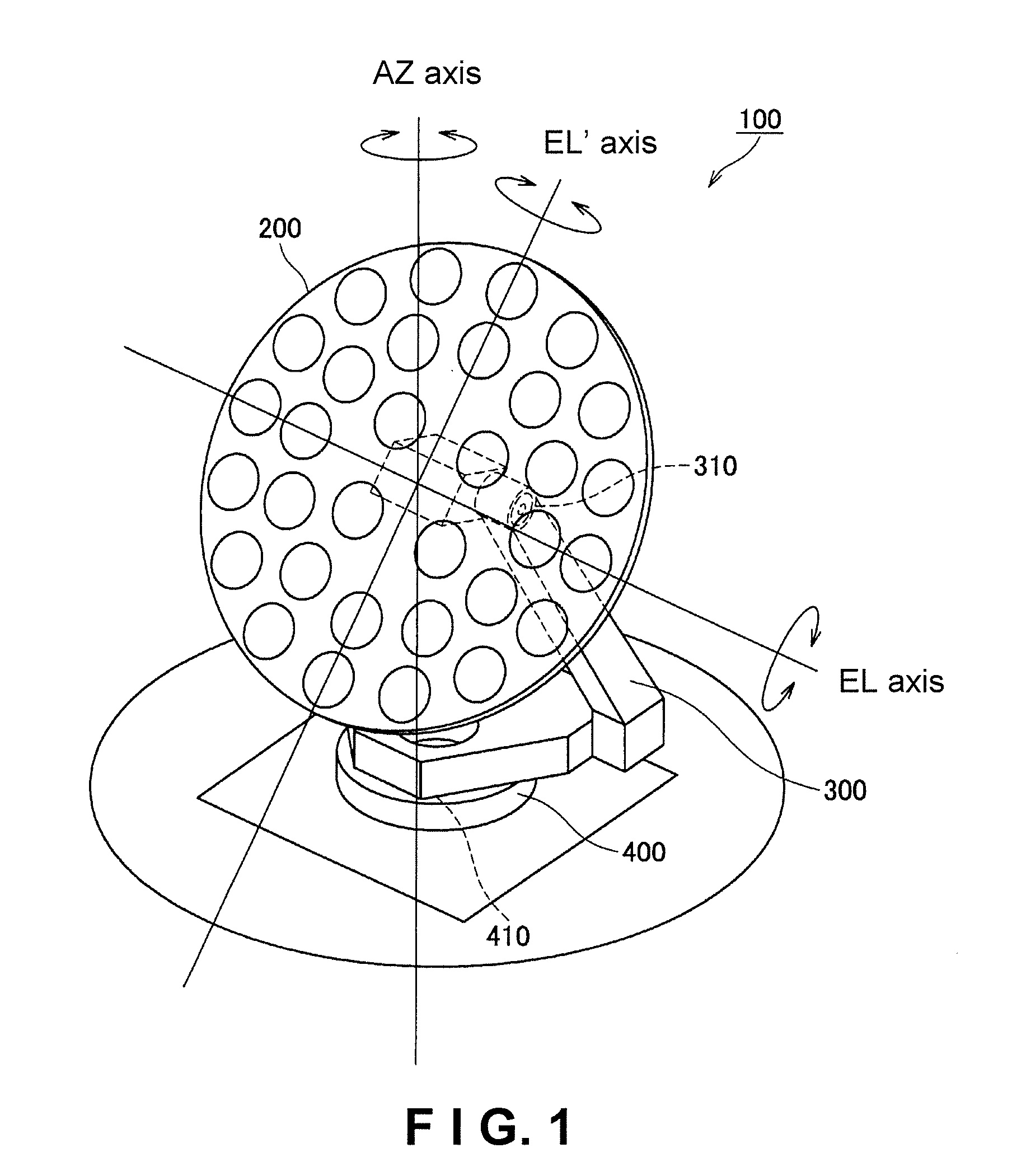
[0037]FIG. 1 is a perspective view showing an example of an external appearance of an antenna apparatus of a two-axis antenna pointing control apparatus according to the present invention. As shown in FIG. 1, an antenna apparatus 100 includes an antenna 200, a support member 300, a rotary pedestal 400, and an antenna pointing control apparatus 500 (not shown).

[0038]A rotary drive apparatus 410 provided in the rotary pedestal 400 of the antenna apparatus 100 serves to move a pointing direction of the antenna 200 about an azimuth axis (hereinafter called “AZ axis”) that extends in a vertical direct...


PUM


Abstract

An antenna pointing control apparatus and method that reduce a pointing error of an antenna having a two-axis gimbal structure. An antenna installed on a ship hull is controlled to point toward a satellite by an antenna pointing control apparatus having a two-axis mechanism. Movement of the ship hull are recognized every prescribed cycle time, a satellite bearing is measured, and a pointing error of a directional antenna with respect to a satellite is detected. If it is determined that the satellite will not pass within a prescribed region A about an extension line of an azimuth angle (AZ) axis of the ship's hull, then a two-axis control is executed. However, if the satellite will pass within the prescribed region A, then a virtual three-axis control is executed.

Description

BACKGROUND[0001]1. Field of the Invention[0002]The present invention relates to a control method for reducing a pointing error of an antenna having AZ (azimuth angle) axis and EL (elevation angle) axis gimbals and to a control apparatus that uses such a control method.[0003]2. Background Information[0004]In order for a mobile station, such as an airplane or a ship, to conduct communications, it is generally necessary for an antenna to be controlled so that it tracks a communication satellite even when the hull is rocking. Methods for tracking a communication satellite include methods that execute control using an antenna tracking mechanism having two axes, three axes, or four axes.[0005]For example, a two-axis mechanism has a turning axis (hereinafter called AZ axis) that is a vertical axis about which the antenna can be turned through a full circle, and a rotation axis (hereinafter called EL axis) that is a horizontal axis about which the antenna can be tilted up and down. The two-...

Claims


Application Information

Patent Timeline
IPC IPC(8): H01Q3/00
CPCG01S3/42H01Q3/08H01Q1/125G01S3/44
Inventor OMORI, GOMATSUYAMA, TOMOYUKIMAENO, HITOSHIADACHI, SATOSHI
Owner FURUNO ELECTRIC CO LTD
Learn More