Zoom lens and imaging apparatus

a technology of zoom lens and zoom lens, which is applied in the field of zoom lens and imaging apparatus, can solve the problems of over-all length being too long, and achieve the effects of reducing the size of the entire lens, good astigmatism correction, and long length

Inactive Publication Date: 2010-10-21
SONY CORP
View PDF26 Cites 8 Cited by
  • Summary
  • Abstract
  • Description
  • Claims
  • Application Information

AI Technical Summary

Benefits of technology

[0025]On the other hand, a value greater than the upper limit in Conditional Expression (4) results in the thickness of the first lens group becoming great, and with a collapsible telescopic arrangement of a zoom lens for an imaging apparatus, the length will be long when storing in a collapsed manner, which is disadvantageous in reducing the size of the entire lens, system.
[0026]Accordin

Problems solved by technology

Particularly, there has been a problem in applications to zoom lenses for imaging apparatuses wherein the lens barrel is a collapsible

Method used


Image

  • Zoom lens and imaging apparatus
  • Zoom lens and imaging apparatus
  • Zoom lens and imaging apparatus

Examples


first embodiment

1. First Embodiment

1-1. Configuration of Zoom Lens

[0055]According to a first embodiment of the present invention, a zoom lens includes a first lens group having negative refractive power, a second lens group having positive refractive power, and a third lens group having positive refractive power, in that order from the object side. At the time of changing power from a wide-angle end state to a tele end state, the first lens group moves such that air space between the first lens group and the second lens group decreases, and air space between the second lens group and the third lens group increases, and the second lens group moves toward the object side. The first lens group includes two lenses, which are, in order from the object side toward the image side, a first lens which is a negative lens of which both faces are formed aspherically with the concave face facing the image side, and a second lens which is a positive meniscus lens of which at least one face is formed aspherically...

first numerical embodiment

2-1. First Numerical Embodiment

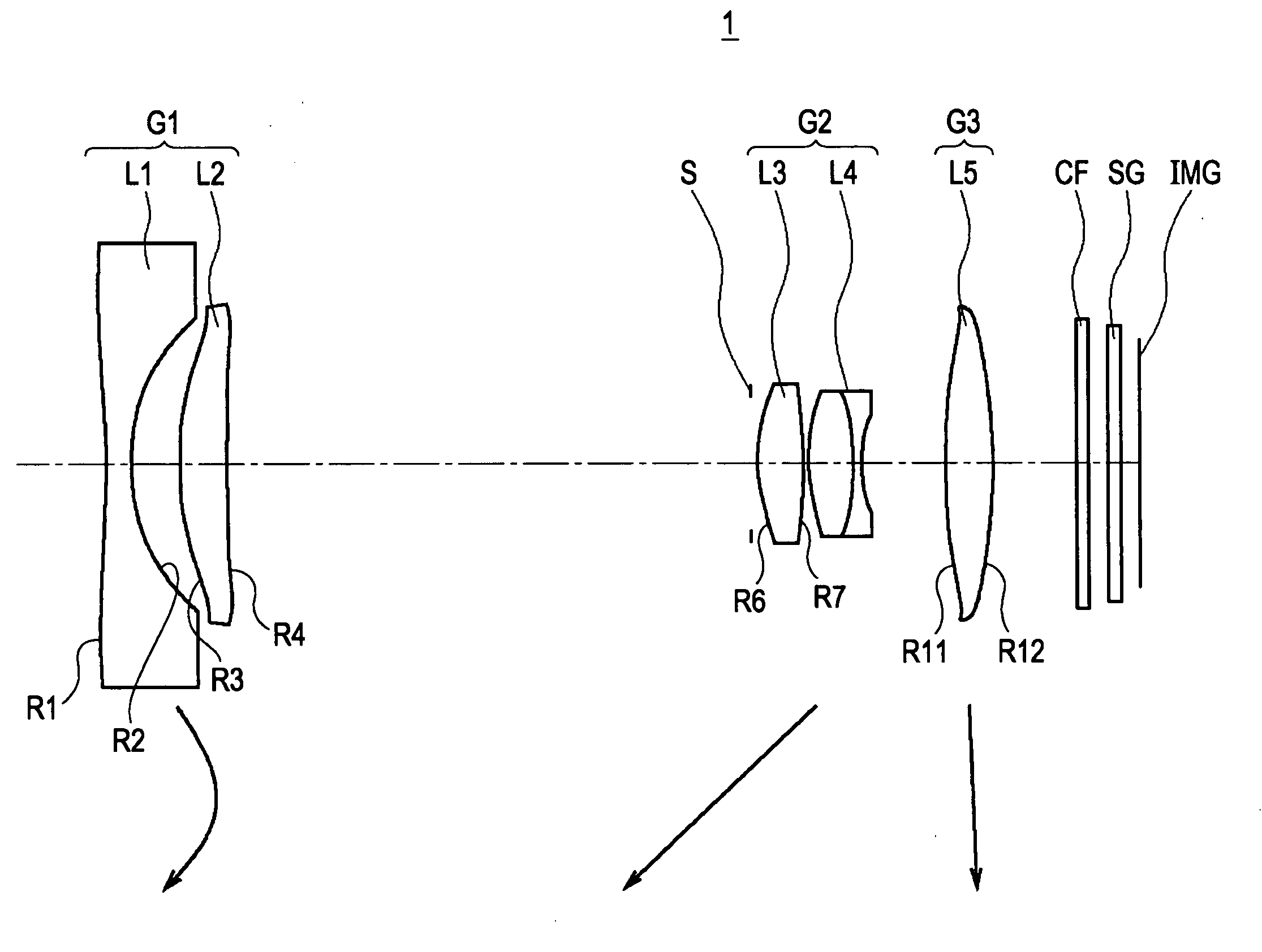
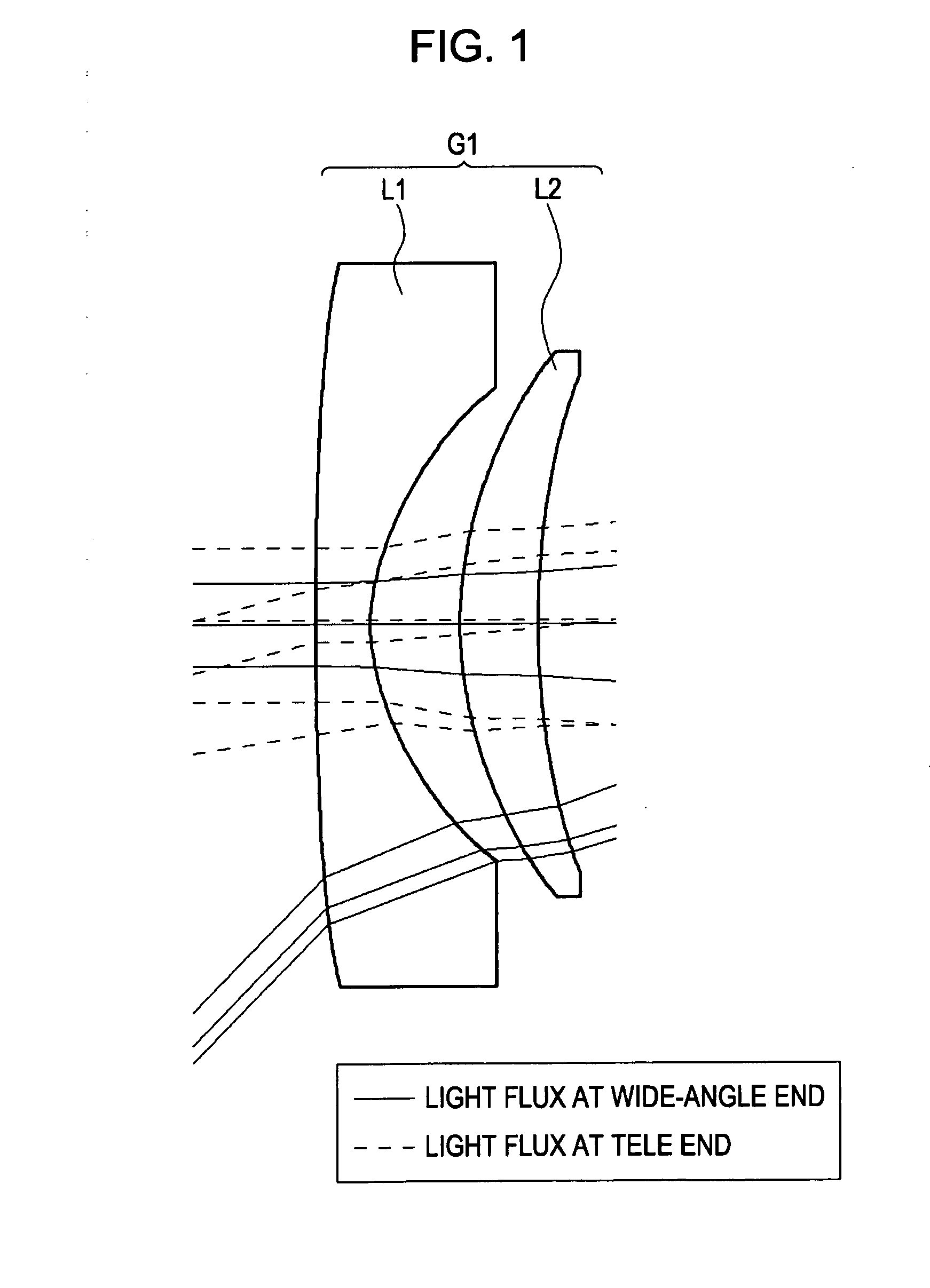
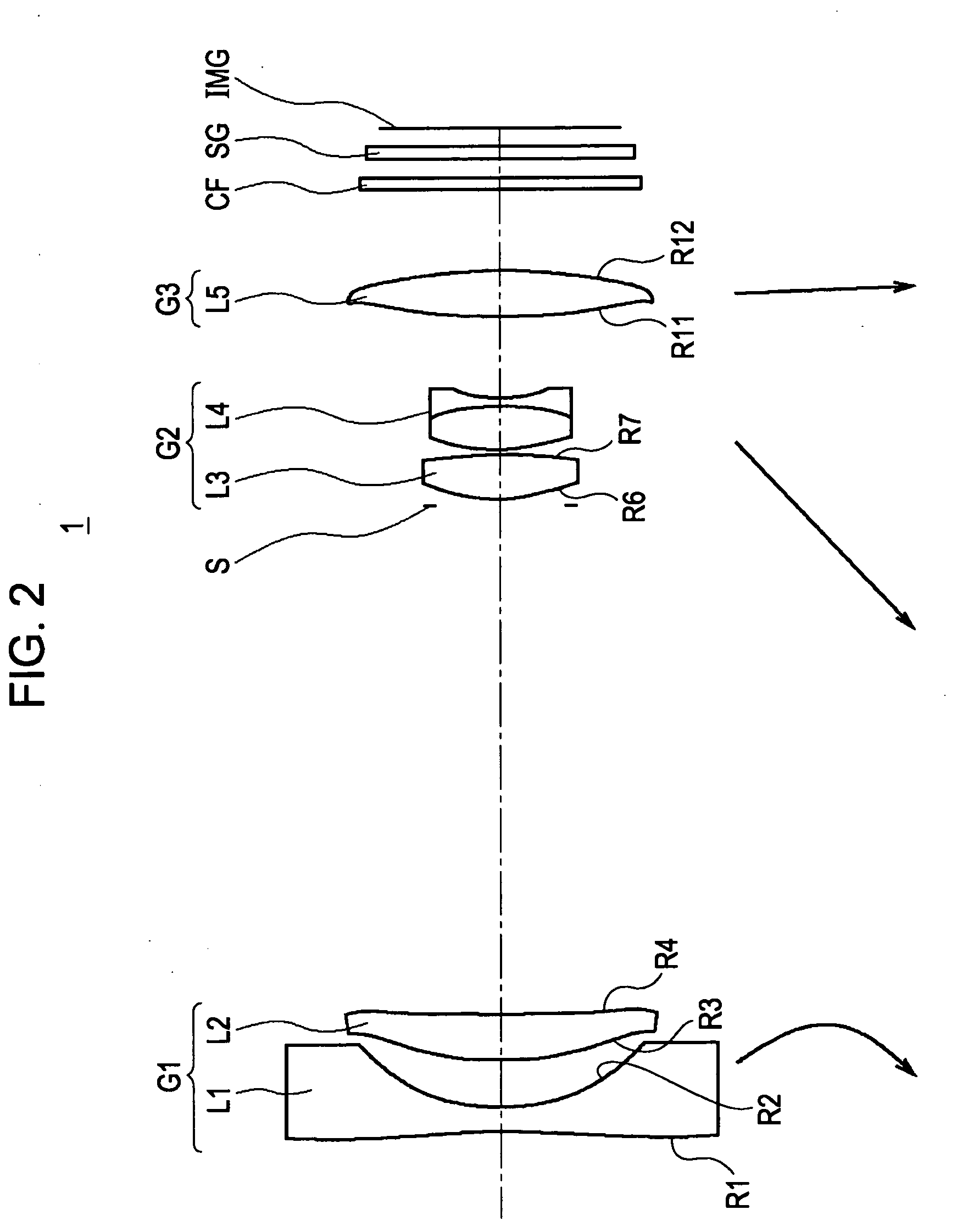
[0089]In FIG. 2, reference numeral 1 denotes a zoom lens according to the First Numerical Embodiment, configured of a first lens group G1 having negative refractive power, a second lens group G2 having positive refractive power, and a third lens group G3 having positive refractive power, in that order from the object side.

[0090]The zoom lens 1 is configured such that, at the time of changing power from the wide-angle end state to the tele end state, the first lens group G1 moves such that air space between the first lens group G1 and the second lens group G2 decreases, and air space between the second lens group G2 and the third lens group G3 increases, and the second lens group G2 moves toward the object side.

[0091]The first lens group G1 includes, in order from the object side toward the image side, a first lens L1 which is a biconcave lens of which both faces are formed aspherically, and a second lens L2 which is a positive meniscus lens of which th...

second numerical embodiment

2-2. Second Numerical Embodiment

[0102]In FIG. 6, reference numeral 2 denotes a zoom lens according to the Second Numerical Embodiment, configured overall of a first lens group G1 having negative refractive power, a second lens group G2 having positive refractive power, and a third lens group G3 having positive refractive power, in that order from the object side.

[0103]The zoom lens 2 is configured such that, at the time of changing power from the wide-angle end state to the tele end state, the first lens group G1 moves such that air space between the first lens group G1 and the second lens group G2 decreases, and air space between the second lens group G2 and the third lens group G3 increases, and the second lens group G2 moves toward the object side.

[0104]The first lens group G1 includes, in order from the object side toward the image side, a first lens L1 which is a biconcave lens of which both faces are formed aspherically, and a second lens L2 which is a positive meniscus lens o...


PUM


Abstract

A zoom lens includes a negative first lens group, a positive second lens group, and a positive third lens group; wherein, when changing power from a wide-angle end state to a tele end state, the first lens group moves such that air space between the first lens group and the second lens group decreases, and air space between the second lens group and the third lens group increases, and the second lens group moves toward the object side; and wherein the first lens group includes a negative lens with both faces formed aspherically and the concave face facing the image side, and a positive meniscus lens with at least one face formed aspherically and the convex face facing the object side, satisfying
2.8<|f1/fw|<3.3
where f1 represents the focal length of the first lens group, and fw represents the entire focal length in the wide-angle end state.

Description

BACKGROUND OF THE INVENTION[0001]1. Field of the Invention[0002]The present invention relates to a zoom lens and an imaging apparatus, and particularly relates to a zoom lens which is compact and has a wide field angle so as to be suitably applied to imaging optical systems of digital input / output equipment such as digital video cameras, digital still cameras and the like, as well has having high optical performance, and to an imaging apparatus using this zoom lens.[0003]2. Description of the Related Art[0004]Imaging apparatuses such as digital still cameras, which use solid-state imaging devices, are coming into widespread use. Demand is increasing for even higher image quality with these imaging apparatuses such as digital still cameras. Particularly, with digital still cameras, there is demand for imaging lenses, zoom lens in particular, having excellent imaging performance capable of handling solid-state imaging devices with a great number of pixels.[0005]There is also strong de...

Claims


Application Information

Patent Timeline
IPC IPC(8): G02B15/177
CPCG02B15/177G02B15/143507
Inventor MATSUI, TAKUMIKANAI, MAKOTOKURODA, DAISUKEYAMANO, HIROKI
Owner SONY CORP
Why Eureka
Try Eureka