Rectangular stacked glass lens module with alignment member and manufacturing method thereof

a technology of stacked glass and lens modules, applied in the field of stacked glass lens modules with alignment members, can solve the problems of difficult cost reduction, lens arrays or lens modules shown, and the yield rate cannot increase, so as to achieve convenient and precise assembly

Inactive Publication Date: 2010-10-21
E PIN OPTICAL IND
View PDF2 Cites 38 Cited by
  • Summary
  • Abstract
  • Description
  • Claims
  • Application Information

AI Technical Summary

Benefits of technology

[0009]It is another object of the present invention to provide a rectangular stacked glass lens module with alignment member and a manufacturing method thereof in which an alignment member is designed as a through hole for convenience of assembly when the stacked lens module array consists of a plurality of optical elements. The through hole is arranged at a non-optical surface of each lens array and a proper position of each optical element. While assembling, the through-hole of the lens array and the through hole of the optical element are positioned over a rod of a jig assembly so as to align the lens array and the optical elements. Thus convenient and precise assembling is achieved.

Problems solved by technology

Therefore, the yield rate is unable to increase and the cost reduction is difficult.
The lens arrays or lens modules shown from FIG. 1 to FIG. 3 still got problems in alignment of optical axes of the lenses.
Thus the improvement of resolution is difficult to achieve.
In the conventional assembling way of projections and holes to form plastic optical lens array, material shrinkage after the plastic injection molding will lead to size change of the projections and the holes.
Thus the location precision is affected and the alignment of the optical axis is difficult.
Therefore, the applications of the plastic optical lens array is limited, especially during manufacturing of small-size lens module, the complicated processes cause cost increase.

Method used


Image

  • Rectangular stacked glass lens module with alignment member and manufacturing method thereof
  • Rectangular stacked glass lens module with alignment member and manufacturing method thereof
  • Rectangular stacked glass lens module with alignment member and manufacturing method thereof

Examples


embodiment 1

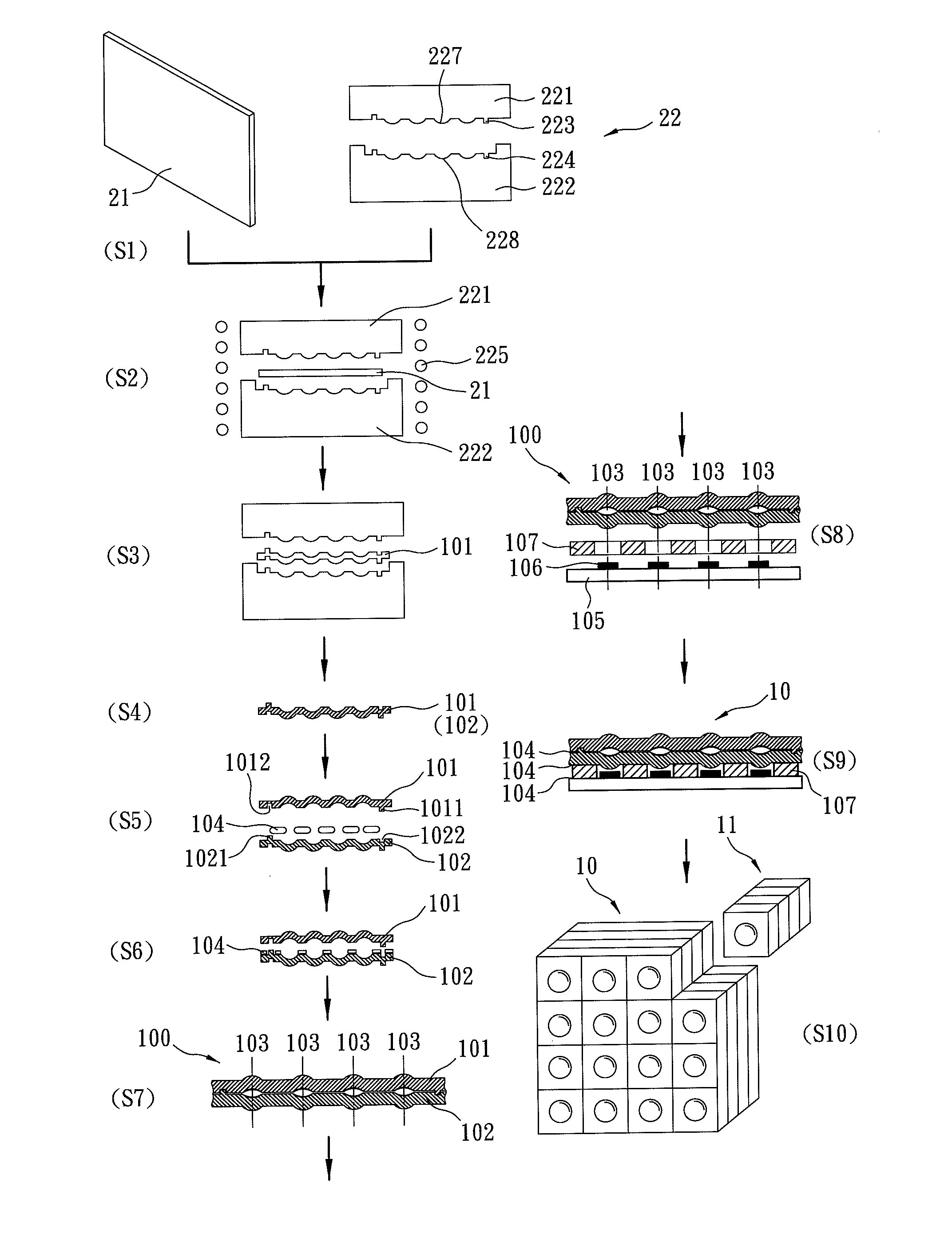
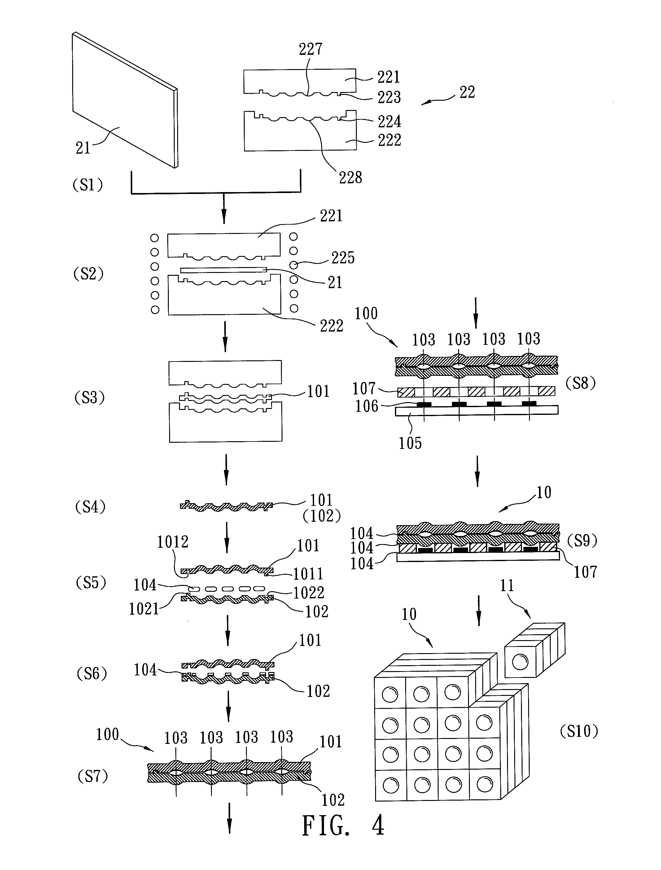
[0026]Refer to FIG. 9, an embodiment of a rectangular stacked lens module 11 including two optical glass lenses 101, 102 is produced by cutting of a stacked lens module array 10. The rectangular stacked lens module 11 generated through cutting of a center part of the stacked lens module array 10 is without alignment member such as columnar alignment pins 1011 / 1021 and corresponding alignment cavities 1022 / 1012. A lens module array 100 includes two lens arrays 101, 102 and four sets of alignment members. The alignment member sets consist of a plurality of columnar alignment pins 1011 / 1021 and corresponding alignment cavities 1022 / 1012. The four sets of alignment members are respectively disposed on four corners of the two lens arrays 101, 102. In FIG. 9, only two sets are revealed. After being aligned by four sets of alignment members, each optical axis 103 of the two lens arrays 101, 102 is aligned. Then UV curing glue 104 is applied to attach and fix the assembly. The alignment mem...

embodiment 2

[0027]Refer to FIG. 7, an embodiment of a rectangular stacked lens module 11 is generated by making straight cutting through a stacked lens module array 10. The stacked lens module array 10 consists of two lens arrays (the first array and the second lens array), four sets of alignment members, a circuit board (the first optical element) 105, a plurality of image sensors (the second optical element) 106, and a plurality of spacers (the third optical element) 107. The four sets of alignment members are four sets of through holes 108. There are only two sets of through holes 108 shown in FIG. 7. The image sensor 106 is corresponding to the optical area (lens) and is preset on the circuit board 105. The circuit board 105 is aligned with the second lens array 102 at a preset interval (by the spacer 107) and is aligned with the first lens array 101 by the through holes 108. After alignment of each optical axis 103 of the lens arrays 101, 102 with each image sensor 106, glue 104 is applied...

embodiment 3

[0028]Refer to FIG. 10, this embodiment of a rectangular stacked lens module 30 is applied to an LED assembly. In an LED assembly, in order to concentrate light from LED chips 35 by optical glass lenses and project light to objectives with a preset distribution pattern, a plurality of optical glass lenses are stacked and spaced at a preset interval. In this embodiment, the rectangular stacked lens module 30 is composed of a first optical glass lens 31, a second optical glass lens 32, a circuit board 36, a LED chip 35, spacers 37 and a silicon layer 38. The optical axes 103 of the two lenses 31, 32 are aligned and there is a certain distance between the two lenses 31, 32. In this embodiment, along the optical axis 103, the distance between a convex surface of the first lens 31 on the light source side and a concave surface of the second lens 32 on the object side is 0.65 mm. The distance between an image side convex surface of the second lens 32 and the LED chip 35 is 3.1 mm. The sil...


PUM

PropertyMeasurementUnit
distanceaaaaaaaaaa
distanceaaaaaaaaaa
optical axisaaaaaaaaaa

Abstract

A rectangular stacked lens module and a manufacturing method thereof are disclosed. The rectangular stacked lens module is produced by cutting straight lines through a stacked lens module array. Firstly, it produces at least two lens arrays. Each lens array includes a plurality of optical lenses by multi-cavity glass molding and at least one alignment member disposed on the non-optical area of the lens array. Then at least the two lens arrays are assembled by the alignment members and are stacked with other optical elements so as to form a stacked lens module array. The optical axis of each optical lens is aligned easily with each other so as to meet requirements for optical precision. Moreover, the manufacturing processes are simplified and the purposes of mass-production and low cost are achieved.

Description

BACKGROUND OF THE INVENTION[0001]The present invention relates to a stacked glass lens module with alignment member and a manufacturing method thereof, especially to a rectangular stacked glass lens module with alignment member and a manufacturing method thereof that are applied to assembled lenses of light emitting diode (LED) light sources, assembled lenses of solar energy conversion systems and optical lenses of cameras and phone cameras.[0002]Glass precision molding technology has been widely applied to manufacture aspherical molded glass lens with high resolution, good stability and low cost such as lens revealed in US2006 / 0107695, US2007 / 0043463, TW095101830, TW095133807, and JP63-295448 etc. A glass preform is set into a mold having an upper mold and a lower mold to be heated and softening. Then the upper mold and the lower mold are assembled correspondingly and apply pressure on the upper mold and the lower mold so as to make the soft glass perform have the same optical surf...

Claims


Application Information

Patent Timeline
Patent Type & Authority Applications(United States)
IPC IPC(8): G02B9/00C03B23/22
CPCC03B11/08C03B2215/414G02B3/0056G02B3/0062G02B13/0085G02B3/0075G02B13/0035G02B13/0045G02B3/0068B29D11/00307
Inventor SHYU, SAN-WOEI
Owner E PIN OPTICAL IND
Why Eureka
Try Eureka