
Confocal photoacoustic microscopy with optical lateral resolution

a photoacoustic microscopy and optical lateral resolution technology, applied in the field of non-invasive imaging, can solve the problems of inability to provide sensitivity, contrast, and spatial resolution sufficient simultaneously, and achieve the effect of reducing the number of instruments and instruments

Active Publication Date: 2010-10-21
WASHINGTON UNIV IN SAINT LOUIS
View PDF20 Cites 133 Cited by
  • Summary
  • Abstract
  • Description
  • Claims
  • Application Information

AI Technical Summary

Problems solved by technology

Existing imaging modalities, however, are unable to simultaneously provide sensitivity, contrast, and spatial resolution sufficient to noninvasively image capillaries.

Method used


Image

  • Confocal photoacoustic microscopy with optical lateral resolution
  • Confocal photoacoustic microscopy with optical lateral resolution
  • Confocal photoacoustic microscopy with optical lateral resolution

Examples


Embodiment Construction

[0026]While the making and using of various embodiments of the invention are discussed in detail below, it should be appreciated that the presently described embodiments provide many applicable inventive concepts that may be embodied in a wide variety of contexts. The embodiments discussed herein are merely illustrative of exemplary ways to make and use embodiments of the invention and do not delimit the scope of the invention.

[0027]To facilitate the understanding of the presently described embodiments, a number of terms are defined below. Terms defined herein have meanings as commonly understood by a person of ordinary skill in the areas relevant to aspects of the invention. Terms such as “a,”“an,”“the,” and “said” are not intended to refer to only a singular entity, but include the general class of which a specific example may be used for illustration and are intended to mean that there are one or more of the elements. The terms “comprising,”“including,” and “having” are intended ...


PUM


Abstract

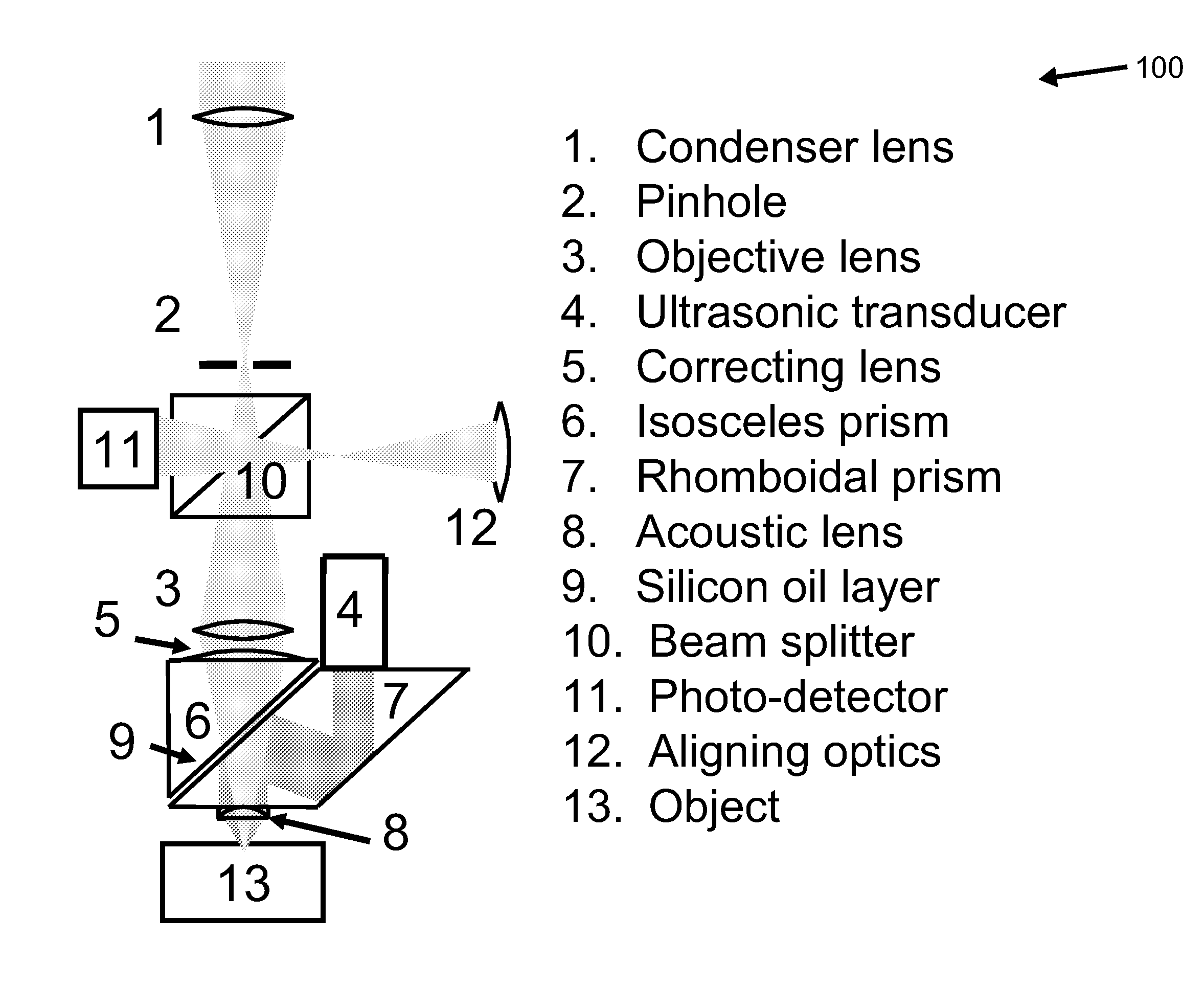
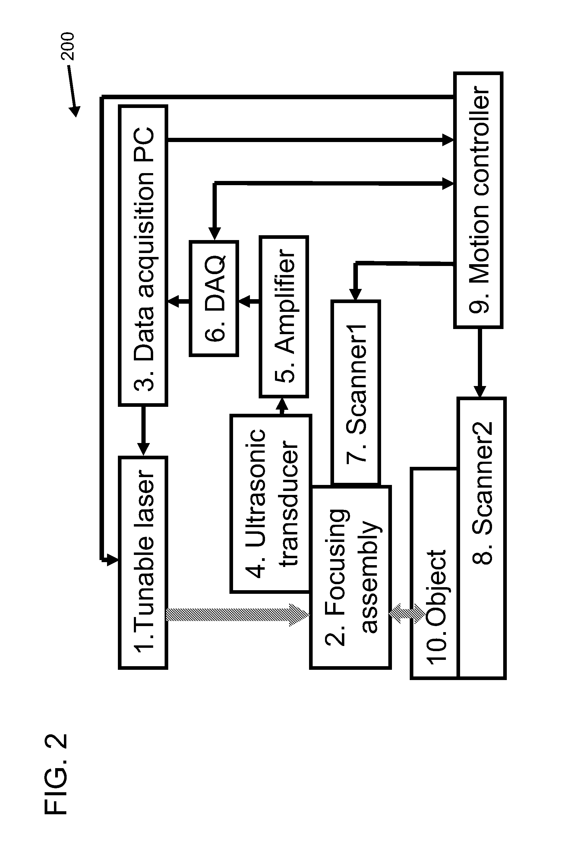
A confocal photoacoustic microscopy system includes a laser configured to emit a light pulse, a focusing assembly configured to receive the light pulse and to focus the light pulse into an area inside an object, an ultrasonic transducer configured to receive acoustic waves emitted by the object in response to the light pulse, and an electronic system configured to process the acoustic waves and to generate an image of the area inside the object. The focusing assembly is further configured to focus the light pulse on the object in such a way that a focal point of the focusing assembly coincides with a focal point of the at least one ultrasonic transducer.

Description

STATEMENT REGARDING FEDERALLY SPONSORED RESEARCH & DEVELOPMENT[0001]This invention was made with government support under grants R01 EB000712 and R01 NS46214, both awarded by the U.S. National Institutes of Health. The government has certain rights in the invention.BACKGROUND[0002]The field of the invention relates generally to noninvasive imaging and, more particularly, to imaging an area with an object using confocal photoacoustic imaging.[0003]The capability of noninvasively imaging capillaries, the smallest blood vessels, in vivo has long been desired by biologists at least because it provides a window to study fundamental physiological phenomena, such as neurovascular coupling, on a microscopic level. Existing imaging modalities, however, are unable to simultaneously provide sensitivity, contrast, and spatial resolution sufficient to noninvasively image capillaries.BRIEF DESCRIPTION[0004]In one aspect, a method for noninvasively imaging a scattering medium is provided. The meth...

Claims


Application Information

Patent Timeline
IPC IPC(8): A61B5/1455G01N29/14G01N21/00
CPCA61B5/0059A61B5/0095G01N21/1702G01N29/0681G01N29/2418A61B8/485G01N2291/02872G02B21/0028G02B21/008A61B5/0082G01N2291/02836
Inventor WANG, LIHONGMASLOV, KONSTANTIN
Owner WASHINGTON UNIV IN SAINT LOUIS
Learn More