Dental surface imaging using polarized fringe projection

a fringe projection and dental surface technology, applied in the field of three-dimensional imaging, can solve the problems of inability to effectively use fringe projection imaging of teeth, inaccurate height data, and inability to accurately detect the height of the tooth, so as to improve the imaging of the tooth surface and reduce the cost

Inactive Publication Date: 2010-10-21
CARESTREAM DENTAL LLC
View PDF24 Cites 77 Cited by
  • Summary
  • Abstract
  • Description
  • Claims
  • Application Information

AI Technical Summary

Benefits of technology

[0012]An advantage offered by the apparatus and method of the present invention relates to improved imaging of tooth surfaces and at lower cost over conventional

Problems solved by technology

However, a number of technical obstacles have prevented effective use of fringe projection imaging of the tooth.
One particular challenge with dental surface imaging relates to tooth translucency.
Translucent or semi-translucent materials in general are known to be particularly troublesome for fringe projection imaging.
Subsurface scattering in translucent structures can reduce the overall signal-to-noise (S/N) ratio and shift the light intensity, causing inaccurate height data.
Another problem relates to high levels of reflection for various tooth surfaces.
In fringe projection imaging overall, contrast is typically poor, with noise as a significant factor.
From an optics perspective, the structure of the tooth itself presents a number of additional challenges for fringe projection imaging.
Moreover, reflection from opaque features beneath the tooth surface can also occur, adding noise that degrades the sensed signal and thus further complicating the task of tooth surf

Method used


Image

  • Dental surface imaging using polarized fringe projection
  • Dental surface imaging using polarized fringe projection
  • Dental surface imaging using polarized fringe projection

Examples


Embodiment Construction

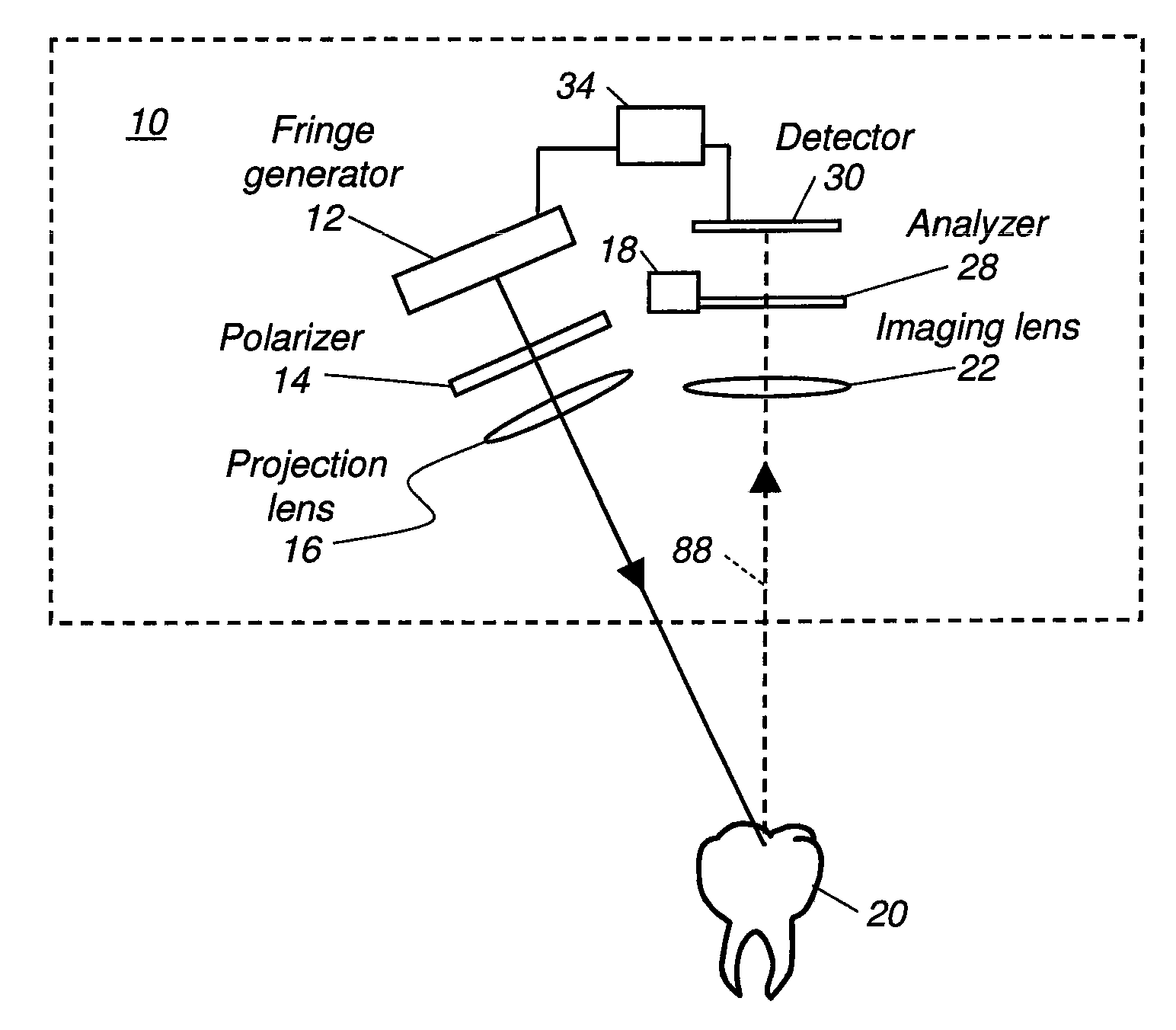
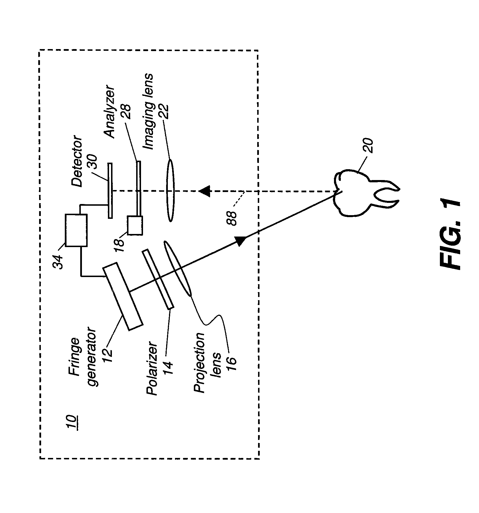
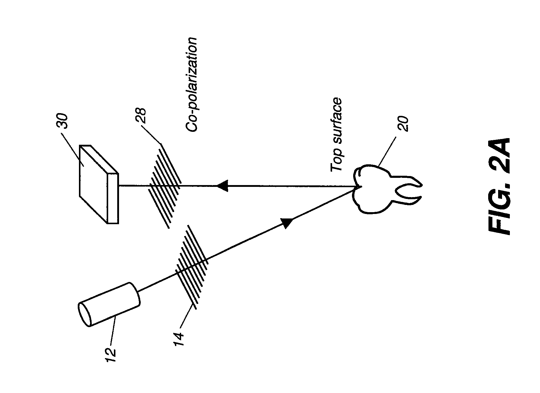
[0030]The figures provided herein are given in order to illustrate key principles of operation and component relationships along their respective optical paths according to the present invention and are not drawn with intent to show actual size or scale. Some exaggeration may be necessary in order to emphasize basic structural relationships or principles of operation. Some conventional components that would be needed for implementation of the described embodiments, such as support components used for providing power, for packaging, and for mounting and protecting system optics, for example, are not shown in the drawings in order to simplify description of the invention itself. In the drawings and text that follow, like components are designated with like reference numerals, and similar descriptions concerning components and arrangement or interaction of components already described are omitted.

[0031]In the context of the present disclosure, the term “fringe pattern illumination” is ...


PUM


Abstract

An intra-oral imaging apparatus having a fringe pattern generator energizable to emit a fringe pattern illumination having a predetermined spatial frequency, with light in the approximate 350-500 nm range. A polarizer in the path of the fringe pattern illumination has a first polarization transmission axis. A projection lens is disposed to direct the polarized fringe pattern illumination as incident illumination toward a tooth surface. An imaging lens is disposed to direct light reflected and scattered at the tooth surface along a detection path. An analyzer is disposed along the detection path, having a second polarization transmission axis. A detector disposed along the detection path obtains image data from the light provided through the analyzer. A control logic processor is responsive to programmed instructions and actuable to adjust the intensity over one or more portions of the fringe pattern illumination according to the image data obtained from the detector.

Description

FIELD OF THE INVENTION[0001]The invention relates generally to the field of diagnostic imaging using structured light and more particularly relates to a method for three-dimensional imaging of the surface of teeth and other structures using fringe projection.BACKGROUND OF THE INVENTION[0002]Fringe projection imaging uses patterned or structured light to obtain surface contour information for structures of various types. In fringe projection imaging, a pattern of lines of an interference fringe or grating is projected toward the surface of an object from a given direction. The projected pattern from the surface is then viewed from another direction as a contour image, taking advantage of triangulation in order to analyze surface information based on the appearance of contour lines. Phase shifting, in which the projected pattern is incrementally spatially shifted for obtaining additional measurements at the new locations, is typically applied as part of fringe projection imaging, used...

Claims


Application Information

Patent Timeline
IPC IPC(8): A61B5/05
CPCA61B1/00009A61C9/006A61B1/247A61B5/0088A61B5/1077A61B5/1079A61B5/4547G01B11/25G01B11/2527G03B15/14G03B35/08G06T7/0014G06T7/0057G06T2207/10016G06T2207/20212G06T2207/30036A61B1/06G06T7/521G01B11/24
Inventor LIANG, RONGGUANG
Owner CARESTREAM DENTAL LLC
Why Eureka
Try Eureka