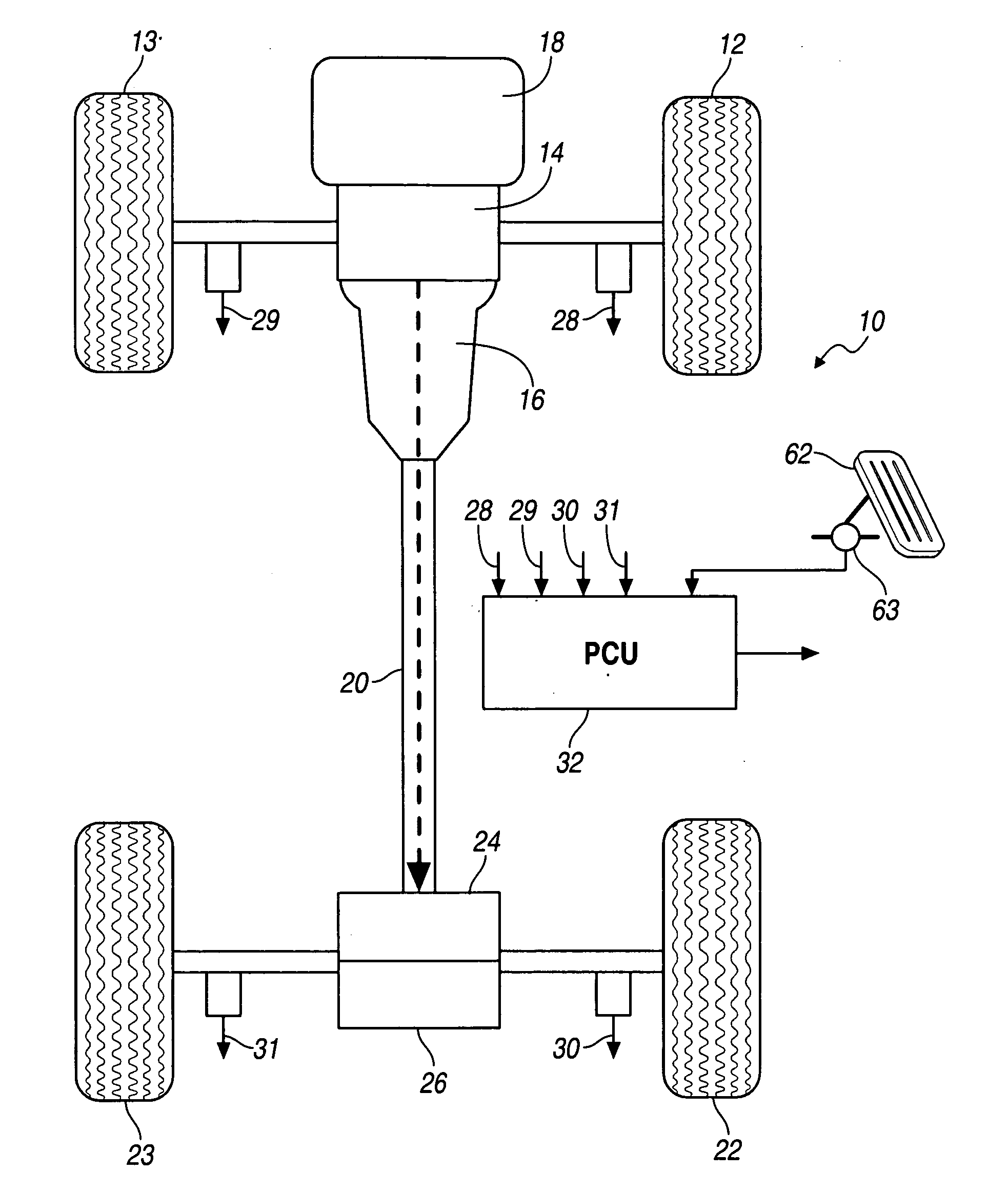
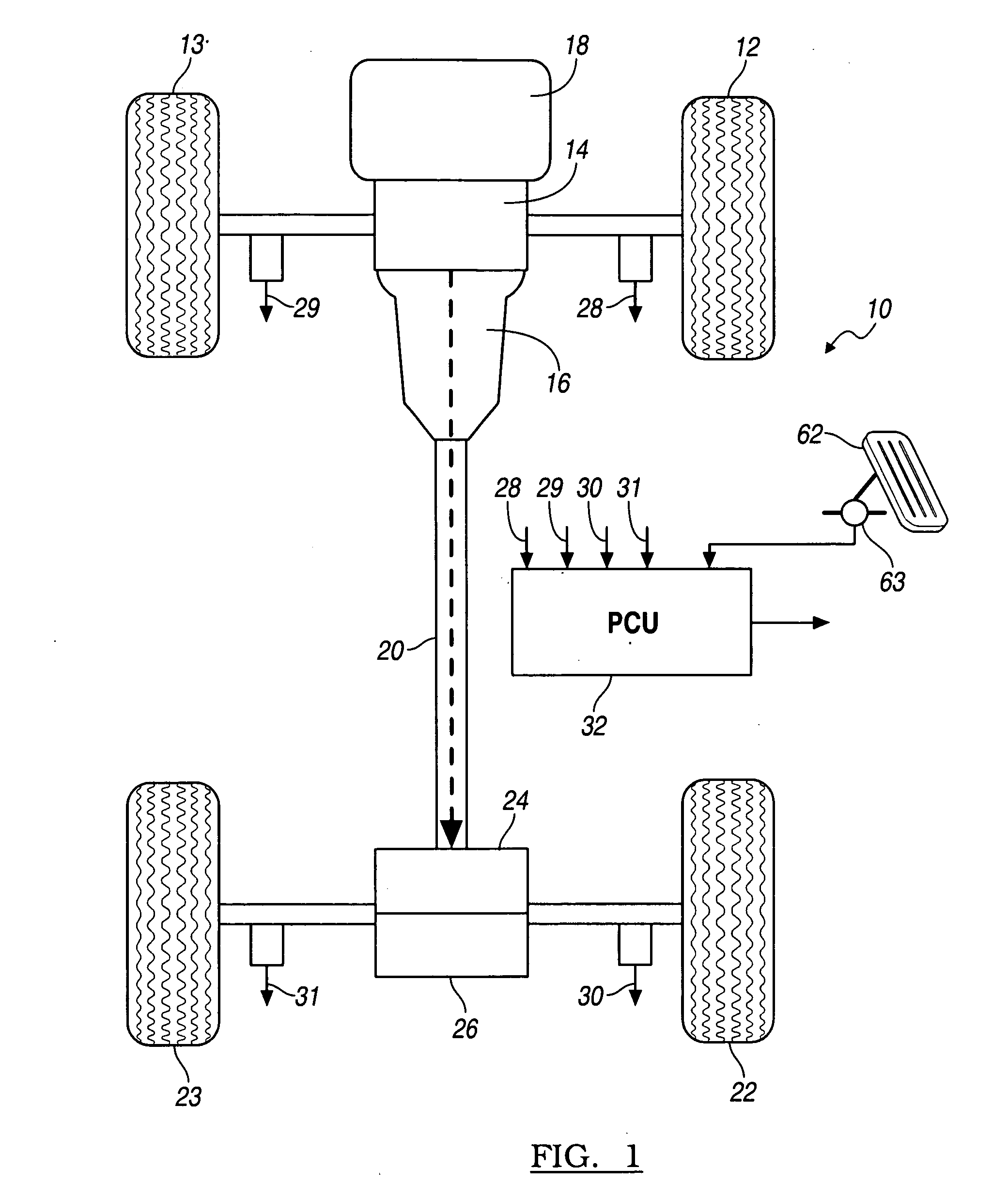
[0017]Referring now to the drawings, there is illustrated in FIG. 1 a motor vehicle driveline 10 equipped with an AWD system. The front wheels 12, 13 are driveably connected to the output of a front axle differential 14, whose input is connect the output of a transmission 16, which produces multiple forward speeds and a reverse drive. The front differential 14 transmits one-half of its input torque to each of the front wheels 12, 13. The transmission is driven by a power source 18, such as internal combustion engine or an electric motor.
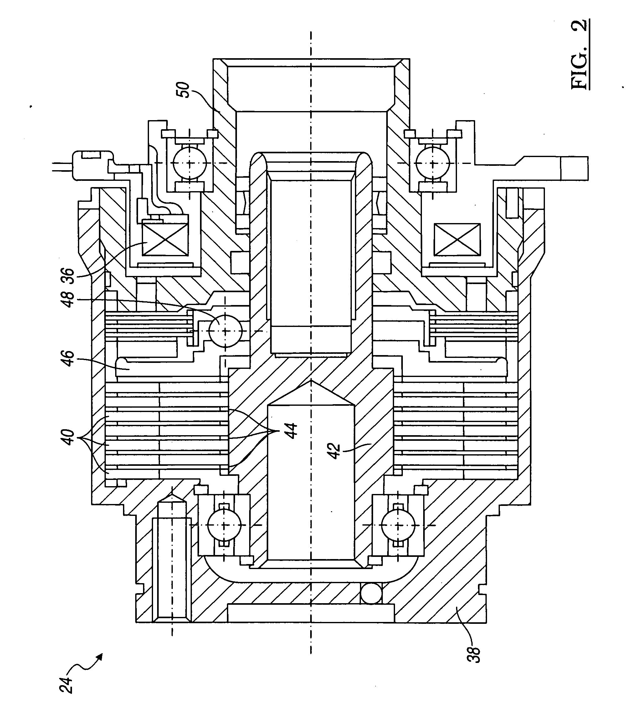
[0018]A driveshaft 20 transmits rotating power from the transmission 16 to the rear wheels 22, 23 through a clutch assembly 24 and a rear inter-wheel differential 26, which transmits one-half of its input torque to each of the rear wheels 22, 23.
[0019]Speed sensors each transmit to a powertrain control unit (PCU) 32, a signal 28-31 representing the rotational speed of a respective front wheel or rear wheel. PCU 32 includes a microprocessor accessible to electronic memory containing constants, variables and parameters related to operation of the vehicle and powertrain, and vehicle control algorithms expressed in computer code, which algorithms are executed repeatedly at frequent intervals.
[0020]FIG. 2 illustrates the clutch assembly 24, whose capacity to transmit torque varies in response to the magnitude of electric current supplied to a coil 36 under the control of PCU 32. A housing 38, secured to driveshaft 20, is secured to a first set of clutch plates 40 by spline at the radial outer periphery of the plates 40, and an intermediate shaft 42 is secured is secured to a second set of clutch plates 44 by spline at the radial inner periphery of the plates 44, which are each located between two of the plates 40.
[0021]When coil 36 is energized, a plate 46, actuated through a ball ramp 48, forces the clutch plates 40, 44 into mutual frictional contact, thereby driveably connecting housing 38 and shaft 42. An output 50, connected to shaft 42, is driveably connected to the input of the rear differential mechanism 26. The operating state of clutch 24 varies among full locked or closed, partially locked or slipping, and fully unlocked or open.
[0022]An algorithm for reducing oscillations in the motor vehicle driveline is illustrated in FIG. 3. A test is performed at step 60 to determine (1) if the average rear wheel speed minus the average front wheel speed is greater than an oscillation control delta reference speed; or (2) if a change during a time period in the average rear wheel speed minus the average front wheel speed) is greater than an oscillation control delta speed rate reference; and (3) the oscillation control algorithm is not active; and (4) the position of the accelerator pedal 62 is greater than a reference pedal position; and (5) vehicle speed is less than a minimum vehicle speed for oscillation control. A sensor 63 produces an electronic signal transmitted as input to the controller 32 representing the extent to which the accelerator pedal 62 is depressed, i.e., the position of the accelerator pedal.
[0023]If the result of test 60 is logically false, control passes to step 64 where execution of the oscillation control algorithm is terminated.
[0024]If the result of test 60 is logically true, at step 66 a flag is set to indicate that the oscillation control is active.
[0025]At step 68, AWD the commanded torque transmitted by clutch 24 to the rear differential 26 is reduced by a magnitude that is proportional to a change in the average rear wheel speed minus the average front wheel speed that occurs during a time interval, whose length is preferably the length of the sampling interval.
[0026]A test is performed at step 70 to determine if the oscillation control is active and the accelerator pedal position is greater than the reference pedal position.
[0027]If the result of test 70 is false, at step 72 a flag is set to indicate that the oscillation control is inactive, and a smooth transition from oscillation control torque of clutch 24 back to normal control is performed. Then control returns to step 64 where execution of the oscillation control algorithm is terminated.
[0028]If the result of test 70 is true, a test is performed at step 74 to determine if the change in the average rear wheel speed minus the average front wheel speed during the most recent sampling interval is less than that change during at least one of the previous sampling intervals.
[0029]If the result of test 74 is false, control returns to step 68.
[0030]If the result of test 74 is true, at step 76 the AWD torque transmitted by clutch 24 is set equal to the commanded torque transmitted by clutch 24 during the previous execution of the oscillation reduction algorithm plus a differential gain multiplied by the change in the average rear wheel speed minus the average front wheel speed during the corresponding sampling interval plus a proportional gain multiplied by the difference between average rear wheel speed—the average front wheel speed.
[0031]At step 78 a test is performed to determine whether the oscillation control AWD commanded torque transmitted by clutch 24 is greater than a reference control AWD commanded torque) or whether the position of accelerator pedal 62 is less than a reference accelerator pedal position.
[0032]If the result of test 78 is false, control returns to step 74.
[0033]If the result of test 74 is true, at step 80 a flag is set indicating that the oscillation control is inactive, and a smoothly transition from oscillation control back to normal control is performed. Thereafter, control returns to step 64.
[0034]The invention has been described with reference to a vehicle in which the principal axle, i.e., the front wheels 12, 13, are continually driven while the vehicle is operating and the secondary axle, i.e., the rear wheels 22, 23, are driven selectively through the clutch assembly under control of the PCU 32. The invention can be applied also to a vehicle whose rear wheels 12, 13 are continually driven while the vehicle is operating and the front wheels 12, 13, are driven selectively through a clutch assembly under control of an electronic controller.
[0035]In accordance with the provisions of the patent statutes, the preferred embodiment has been described. However, it should be noted that the alternate embodiments can be practiced otherwise than as specifically illustrated and described.