Air-conditioning with dehumidification

a technology of air conditioner and dehumidification, which is applied in the direction of refrigeration components, computer control, stationary plate conduit assemblies, etc., can solve the problems of reducing the energy consumption of cooling, reducing the humidity of the air conditioner, and not willing to evaporate sweat of the hundred percent of the humidity, so as to increase the airflow rate and increase the humidity. , the effect of increasing the humidity

Inactive Publication Date: 2010-10-28
MOORE STEVEN CLAY
View PDF27 Cites 19 Cited by
  • Summary
  • Abstract
  • Description
  • Claims
  • Application Information

AI Technical Summary

Benefits of technology

[0079]Some embodiments may comprise a method for creating a design for manufacturing of an opposing direction evaporator coil unit, the method comprising: generating a schematic for interconnecting coils having one general direction of flow from a first end of each of the coils to a second end of each of the coils, wherein interconnecting comprises coupling the first end of each of the coils with an inlet coupling and coupling a second end of each of the coils with an outlet coupling to facilitate flow of refrigerant through the first end of each of the coils to the second end of each of the coils; and generating a schematic for mounting the coils in a frame to create the opposing direction evaporator coil unit with interconnections of the schematic for interconnecting the coils.
[0130]Some embodiments may comprise an air-conditioning system where a microprocessor or other intelligent / sophisticated controller is incorporated to maintain the exit air temperature close to freezing by one or more or all of the following functions: adjusting the airflow rate through the opposing direction evaporator coil; increasing the airflow rate in response to an instruction to increase humidity; reversing the airflow direction through the opposing direction coil to increase humidity; cycling between fast and slow airflow rates; cycling between forward and reverse airflow directions through the opposing direction evaporator coil; cycling the compressor on and off to freeze and melt ice to maintain an air exit temperature from the evaporator coil at or close to 0° C.; to vary fan speed or louver position; which in-turn varies air-flow rate, and where zero may be one of the settings; switching between fast and slow airflow rates, the switching frequency being fast enough to maintain air exit temperature within a relatively narrow and acceptable band; setting the temperature of evaporation of the cooling fluid close to 0° C. so as to avoid ice build up on the evaporator coil while maintaining the ability to cool air to close to freezing temp; and setting the temperature of evaporation of the refrigerant close to 0° C. with sufficient thermal gradient / resistance between air and refrigerant to work at roughly −2° C. to +6° C. for the boiling temp of the liquid refrigerant in the evaporator coil.

Problems solved by technology

Conversely, warm air at one hundred percent humidity will not be willing to evaporate any sweat and no cooling will be provided.
This will cut their energy use for cooling.
For example, repositioning the one or more louvers may incrementally affect the amount of airflow across the coils and the amount of airflow that bypasses the coils.

Method used


Image

  • Air-conditioning with dehumidification
  • Air-conditioning with dehumidification
  • Air-conditioning with dehumidification

Examples


Embodiment Construction

[0147]The following is a detailed description of novel embodiments depicted in the accompanying drawings. However, the amount of detail offered is not intended to limit anticipated variations of the described embodiments; on the contrary, the claims and detailed description are to cover all modifications, equivalents, and alternatives falling within the spirit and scope of the present teachings as defined by the appended claims. The detailed descriptions below are designed to make such embodiments understandable to a person having ordinary skill in the art.

INTRODUCTION

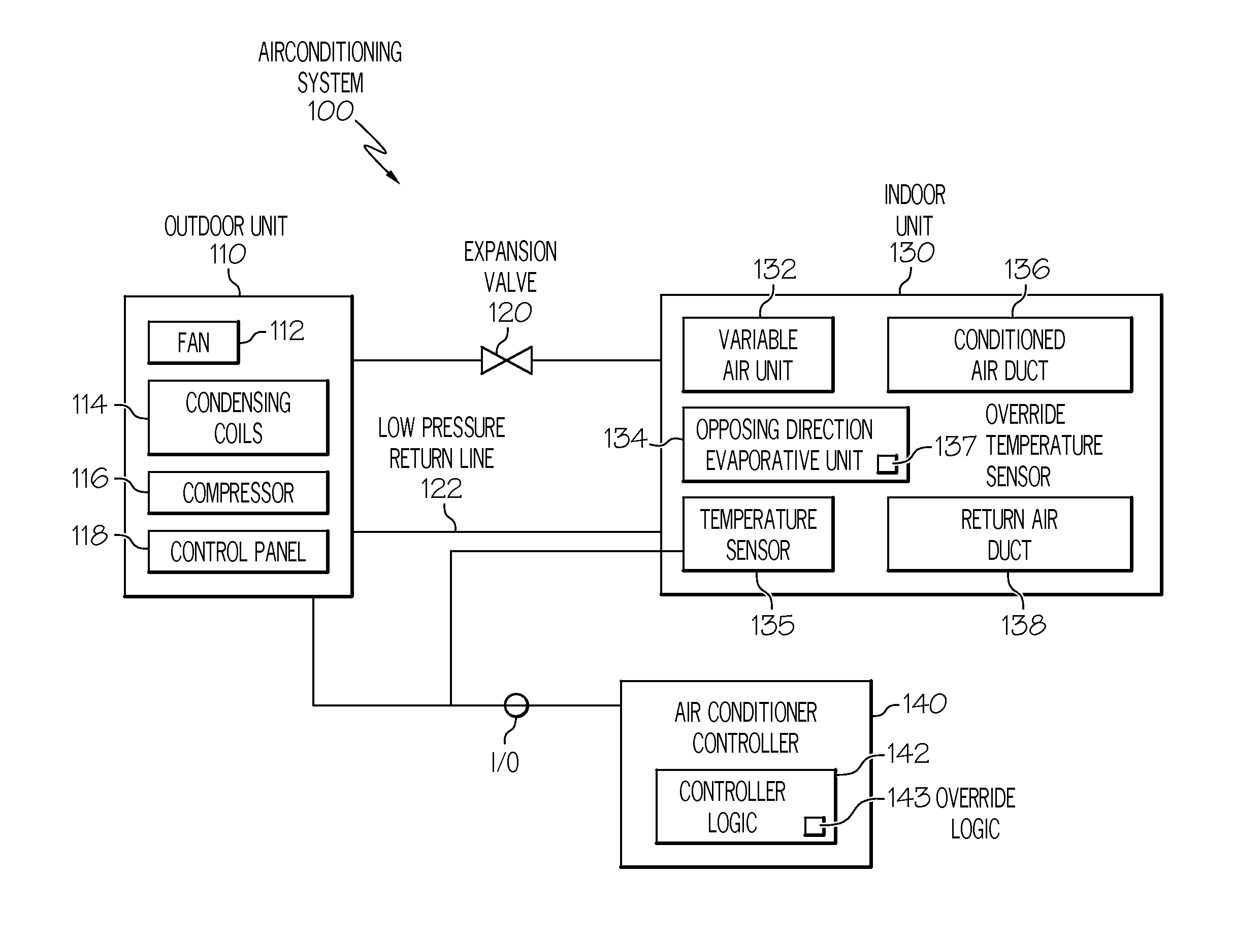
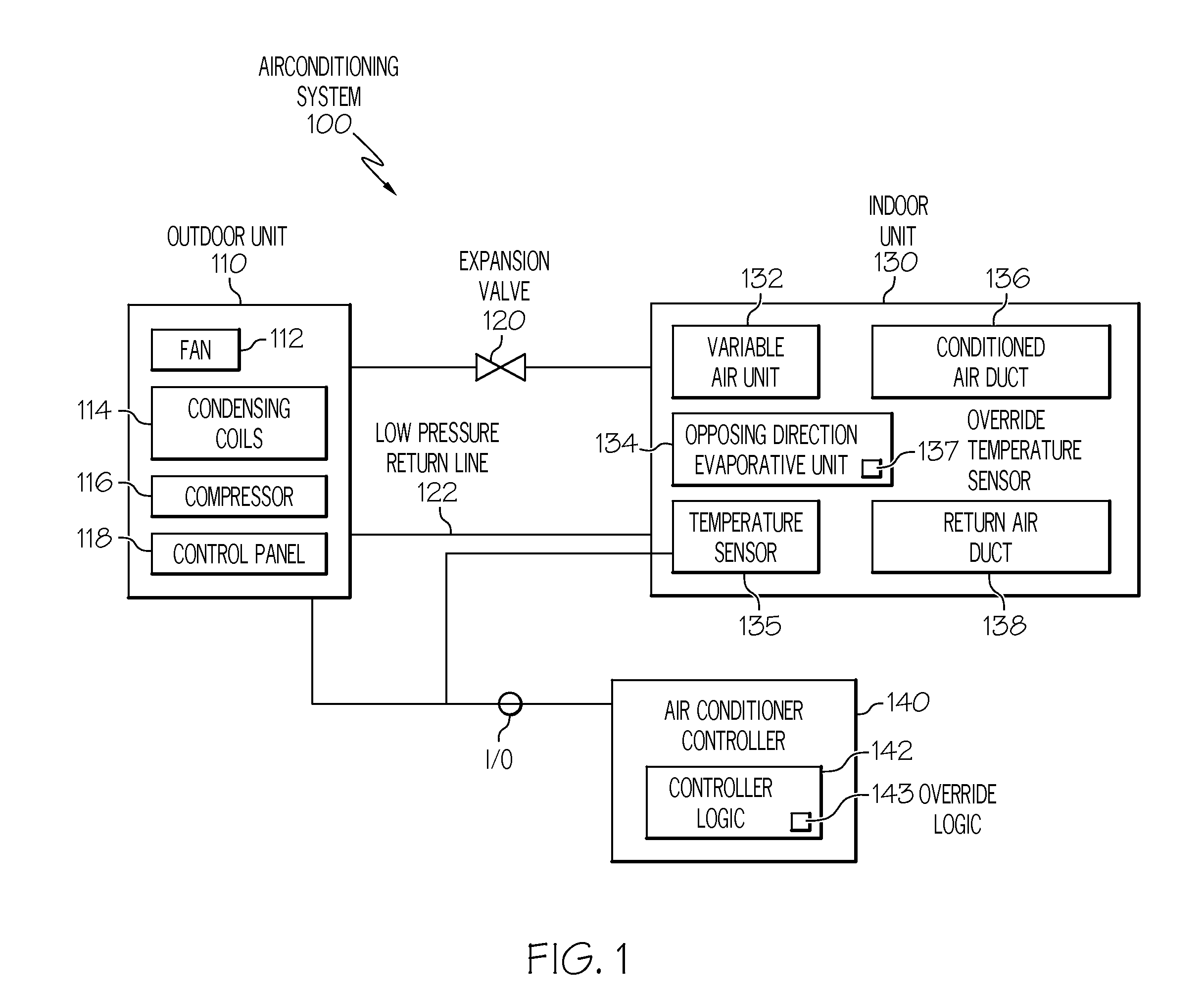
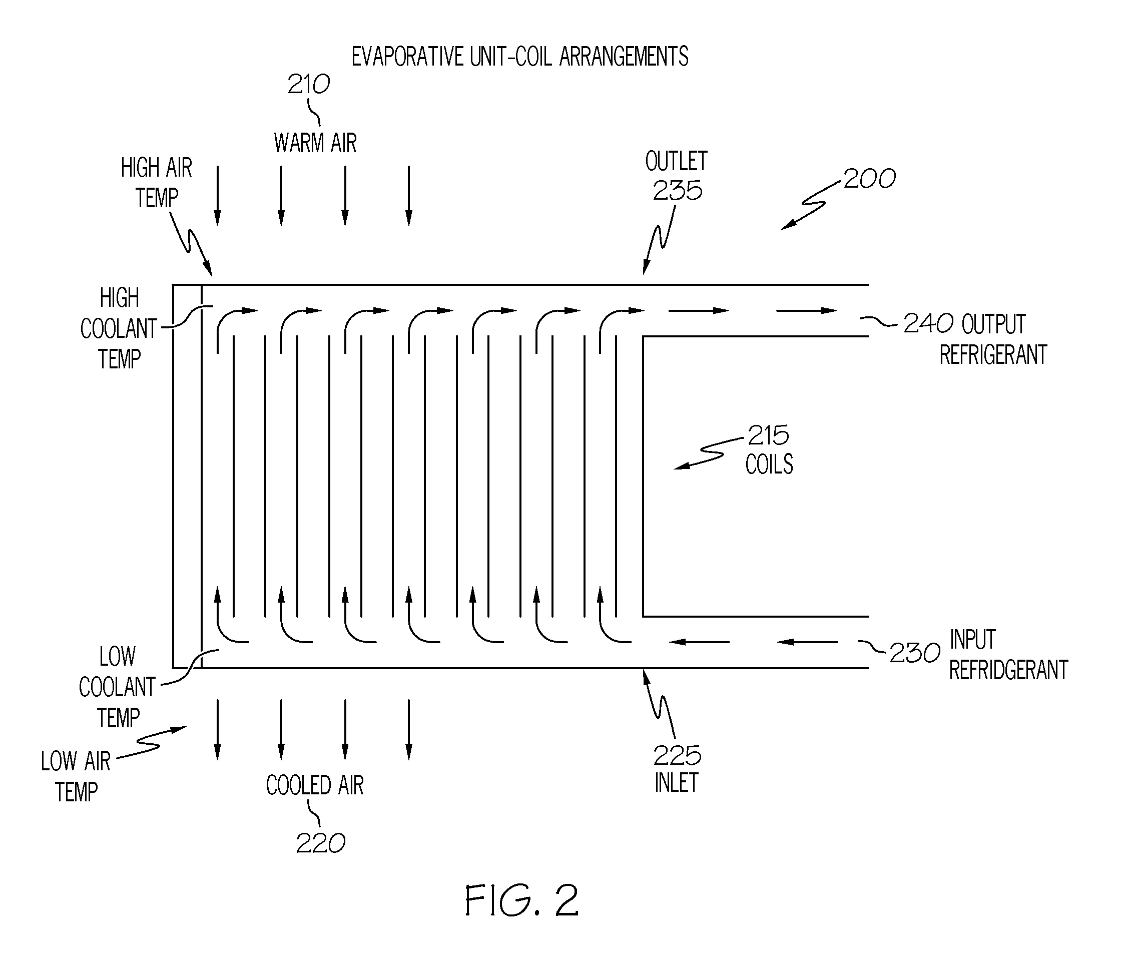
[0148]Generally, air-conditioning with dehumidification is described herein. Embodiments may involve methods and arrangements that utilize or comprise logic such as hardware and / or code for cooling and dehumidifying outgoing air. Some embodiments comprise an opposing direction, evaporative unit. The opposing direction, evaporative unit uses what may be referred to as an opposing direction flow, which directs airflow ac...


PUM

PropertyMeasurementUnit
temperatureaaaaaaaaaa

Abstract

One embodiment comprises an apparatus with an evaporative unit for a refrigerant having a flow direction opposing the airflow direction and an adjustable airflow rate to utilize to produce both cold / dehumidified exit air and warmed exit refrigerant for high efficiency and to maintain an airflow sufficient to avoid freeze-up of evaporative unit or freeze-up to an extent that blocks the airflow. This may produce low humidity even when the room thermostat is set warm (e.g. 85 F) and 5%-30% lower A / C bills. Other embodiments comprise systems and methods related to the adjustable airflow. A further embodiment comprises a controller to adjust the humidity in an air-conditioned space to produce air, which is both temperature and humidity controlled.

Description

BACKGROUND[0001]The present invention is in the field of air conditioners (A / Cs), and more specifically in the field of evaporator coils which achieve more air dehumidification.[0002]Standard A / C units are not designed to produce the lowest easily achievable humidity because when indoor space is cooled to the typical desired temperature, 70-72 degrees Fahrenheit (° F.), dehumidification is sufficient and indeed, at the normal temperature in air conditioned space, lower humidity would be undesirable because the combination of low humidity and 72° F. temperature air would make most people feel uncomfortably cold. Typical air conditioner coils rely on a relatively large volume of airflow through a large but relatively thin coil to exchange heat from the Freon, R-22 or other refrigerant, as it boils inside the coil tubing, to the air passing through the coil fins.[0003]Standard evaporator coils use flow patterns such that the refrigerant flows through the coil perpendicularly to air. Si...

Claims


Application Information

Patent Timeline
Patent Type & Authority Applications(United States)
IPC IPC(8): F25D17/06F28F13/00F28F9/02F28F1/36F25B39/02B23P15/26F25B1/00G05B15/00F25D23/00
CPCF24F3/1405F25B39/02F25B47/006F25B2600/112Y10T29/49359F28D9/0025F28F3/046Y02B30/743F25B2700/21175Y02B30/70
Inventor MOORE, STEVEN CLAY
Owner MOORE STEVEN CLAY
Why Eureka
Try Eureka