Electric power conversion apparatus for vehicle

Active Publication Date: 2010-10-28
DENSO CORP
View PDF13 Cites 23 Cited by
  • Summary
  • Abstract
  • Description
  • Claims
  • Application Information

AI Technical Summary

Benefits of technology

[0007]It is therefore an object of the present invention to provide an electric power conversion apparatus, which is capable of maintaining

Problems solved by technology

If such a mechanical relay is used, reliability of its operation is lowered by foreign matters and the like, which are often jammed.
If a current required by the electric motor is increased, th

Method used


Image

  • Electric power conversion apparatus for vehicle
  • Electric power conversion apparatus for vehicle
  • Electric power conversion apparatus for vehicle

Examples


Example

First Embodiment

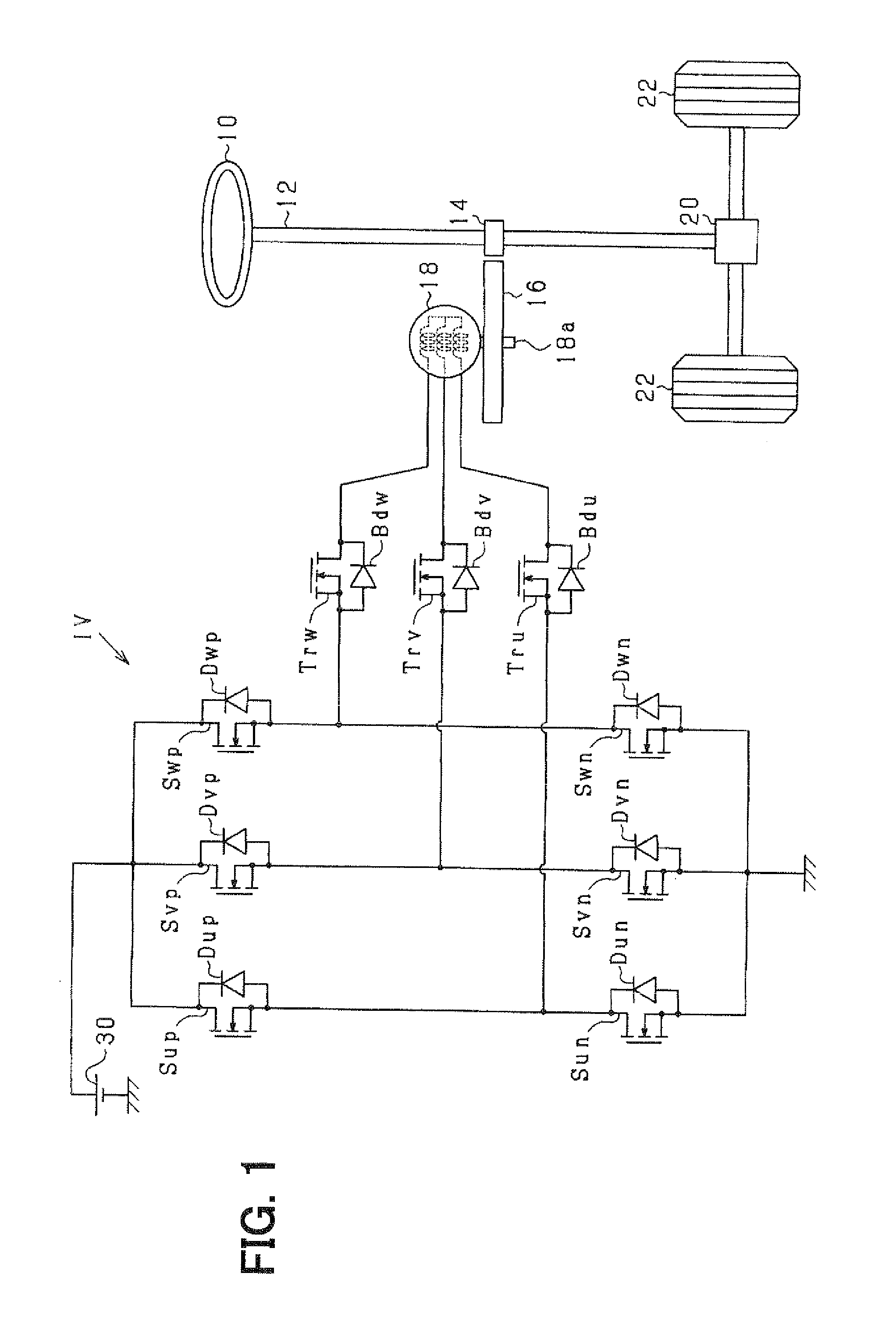
[0015]Referring first to FIG. 1, a steering system for a vehicle provided as an in-vehicle device includes a steering wheel 10, an input shaft 12, a transmission 20, drive wheels 22 and the like. The steering wheel 10 is operable by a driver to change direction of travel of the vehicle. The input shaft 12 is rotatable in accordance with rotation operation of the steering wheel 10. The input shaft 12 is mechanically coupled with a main gear 14 to rotate together about the same rotation axis.

[0016]The main gear 14 is engaged with an assist gear 16. The assist gear 16 is mechanically coupled with an output shaft 18a of an electric motor 18 to rotate together about the same rotation axis.

[0017]The input shaft 12 is also mechanically coupled to the transmission 20 at its end, which is opposite to the steering wheel 10. The transmission 20 is provided to transfer the rotation of the input shaft 12 to the drive wheels by changing a ratio of the rotation. Thus, the steering ...

Example

Second Embodiment

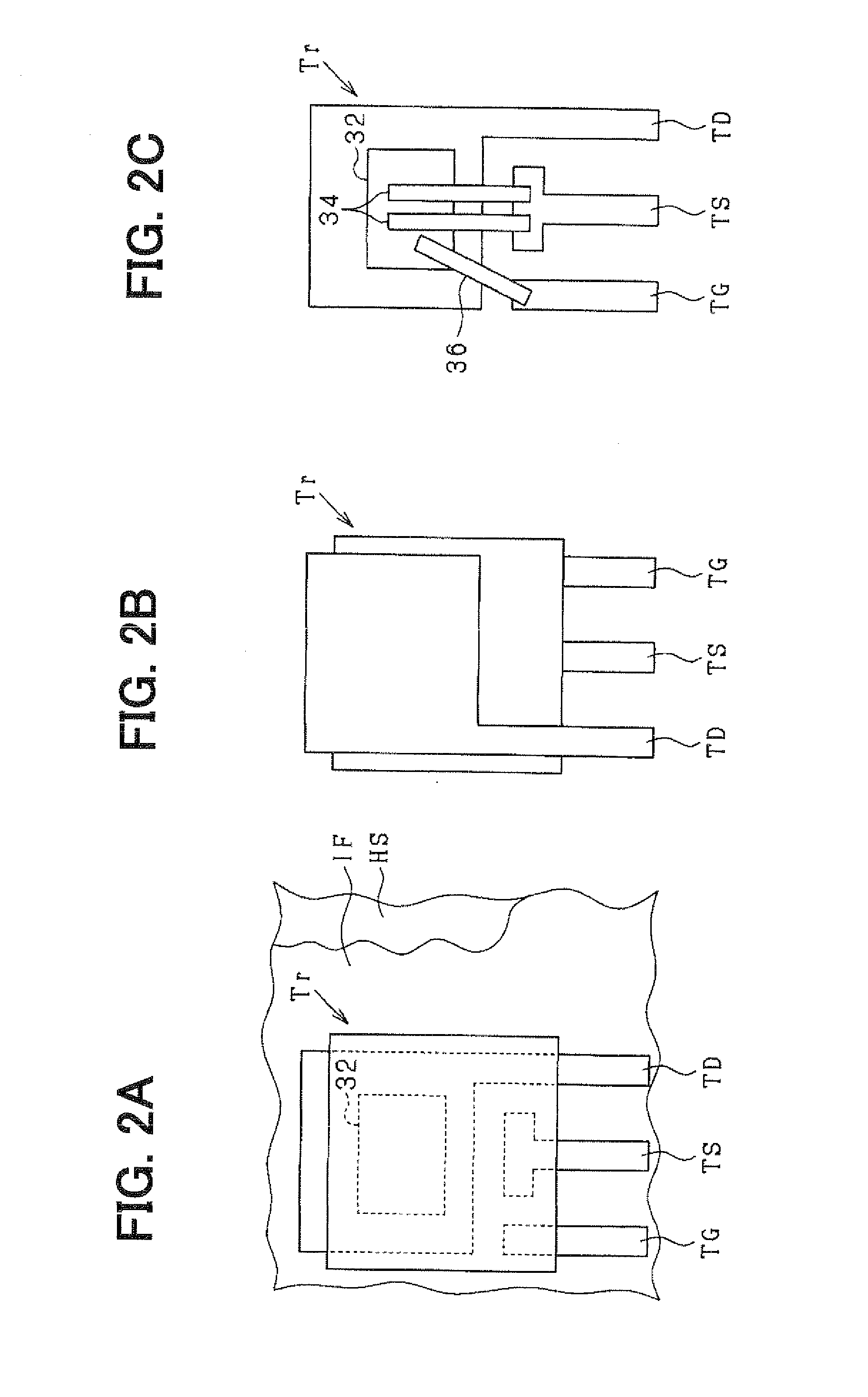
[0032]An electric power conversion apparatus according to the second embodiment is shown in FIG. 3, in which the same or similar parts are designated by the same reference numerals as in the first embodiment.

[0033]In the second embodiment, the drains of the semiconductor relays Tru, Trv, Trw are connected to the output terminals of the inverter circuit IV. As a result, even if the electric path between the semiconductor relay Tr and the electric motor 18 is short-circuited to the ground, it is prevented that a short-circuit current flows from the battery 30 to the ground through the diode Bd of the semiconductor relay Tr. Since the drain of the semiconductor relay Tr has higher heat radiation performance, heat radiation at the inverter circuit IV side can be promoted by arranging the drain at the inverter circuit IV side.

[0034]The second embodiment has the following features in addition to the features (1) and (2) of the first embodiment.

(4) Each of the output termi...

Example

[0035]The first and the second embodiments may be modified as follows.

[0036]The transistor provided as the semiconductor relay Tr in each electric path between the inverter circuit IV and the electric motor 18 is not limited to one in number. For example, as shown in FIGS. 4A and 4B, a pair of transistors Tr1 and Tr2 may be provided as the semiconductor relay Tr in each electric path or phase of the electric motor 18. In these examples, the transistors Tr1 and Tr2 in each electric path are connected such that the anodes of respective body diodes Bd1 and Bd2 of the transistors Tr1 and Tr2 are connected to each other as shown in FIG. 4A or the cathodes of the same are connected to each other as shown in FIG. 4B. According to this arrangement, electrical connection between the inverter circuit IV and the electric motor 18 can be surely shut off. In the example of FIG. 4A, the drain of one of the transistors Tr1 and Tr2, specifically transistor Tr2, is connected to the electric motor 18...


PUM


Abstract

In an electric power steering system, a drain terminal side of a semiconductor relay is positioned to face a heat sink through an insulation film layer. The semiconductor relay has a source terminal between a gate terminal and a drain terminal. The source terminal is provided between the gate terminal and the drain terminal with respect to parts of the gate terminal, the drain terminal and the source terminal, which extend generally in parallel each other on the same plane.

Description

CROSS REFERENCE TO RELATED APPLICATION[0001]This application is based on and incorporates herein by reference Japanese Patent Application No. 2009-106493 filed on Apr. 24, 2009.FIELD OF THE INVENTION[0002]The present invention relates to an electric power conversion apparatus, which is connected to an electric motor used as an actuator for an in-vehicle device such as an electric power steering system for a vehicle.BACKGROUND OF THE INVENTION[0003]In a conventional electric power conversion apparatus, mechanical relays are used to shut off electric connection between motor phase terminals of a three-phase electric motor and output terminals of an inverter circuit. If such a mechanical relay is used, reliability of its operation is lowered by foreign matters and the like, which are often jammed. The following patent document therefore proposes to use a power MOS-type field effect transistor in place of such a mechanical relay.[0004][Patent document] JP 2006-21645A[0005]According to t...

Claims


Application Information

Patent Timeline
IPC IPC(8): H02P6/14B62D5/04H01L29/78H02M7/48
CPCB62D5/0463H02P27/06H01L2924/0002H01L2924/00
Inventor TSUBOI, TAKASHIMASE, KATSUHISATODA, YASUYOSHI
Owner DENSO CORP
Why Eureka
Try Eureka