In-vehicle power transmission device and power transmission system for vehicle

a technology of power transmission device and in-vehicle power source, which is applied in the direction of dynamo-electric gear control, transportation and packaging, gear control, etc., can solve the problems of increasing the total parts of the hybrid vehicle, unable to use the torque produced by the in-vehicle power source to operate the compressor, and inefficient energy use of the internal combustion engin

Inactive Publication Date: 2010-10-28
NIPPON SOKEN
View PDF9 Cites 20 Cited by
  • Summary
  • Abstract
  • Description
  • Claims
  • Application Information

AI Technical Summary

Benefits of technology

[0034]The second rotor lies at a middle in speed in the nomographic chart between the two of the power split rotors connected mechanically to the electric rotating machine. This enables the speed of the second rotor to be brought into agreement with zero (0) or any value other than zero (0) even when the speed of the electric rotating machine is not zero (0).
[0035]The power split rotors also work to power among the driven wheel of the vehicle, the electric rotating machine, and an internal combustion engine. One of the three or more power split rotors which lie in speed on the straight line in the nomographic chart is the second rotor. At least two of the three of more power split rotors which lie in speed on the straight line in the nomographic chart are connected mechanically to the electric rotating machine. The power transmission apparatus also includes a first power transmission mechanism and a second power transmission mechanism. The first power transmission mechanism works to selectively establish and block transmission of power between a rotating shaft of the internal combustion engine and one of the power split rotors which is other than the first rotor and serves as an engine starting rotor whose speed lies at a middle of the speeds of the power split rotors

Problems solved by technology

The hybrid vehicles are typically controlled to stop the internal combustion engine in a low speed running range in view of the fact that the internal combustion engine is usually inefficient in energy use in the low speed running range.
It is, thus, impossible to use the torque produced by the in-vehicle power source to operate a compressor of an air conditioner mounted in the vehicle when the vehicle is at a stop.
The use of the above addi

Method used


Image

  • In-vehicle power transmission device and power transmission system for vehicle
  • In-vehicle power transmission device and power transmission system for vehicle
  • In-vehicle power transmission device and power transmission system for vehicle

Examples


first embodiment

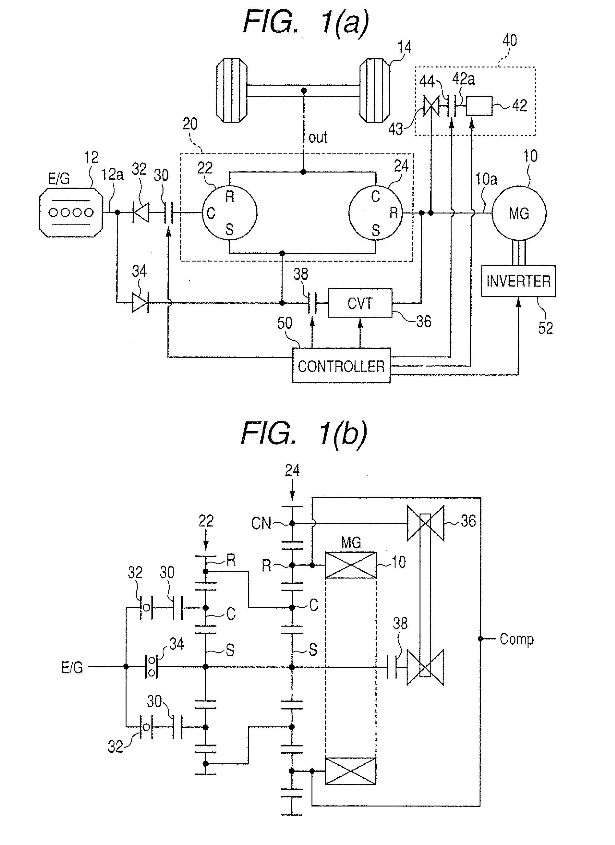
[0087]Referring to the drawings, wherein like reference numbers refer to like parts in several views, particularly to FIGS. 1(a) and 1(b), there is shown a hybrid system including an in-vehicle power control system equipped with an in-vehicle power transmission device according to the invention. The in-vehicle power transmission device of this invention may alternatively be used with either an electric vehicle (EV) equipped only with an electric motor as a power source for running a road wheel. The power control system is equipped with the power transmission device and a controller working to control an operation of the power transmission device. The power control system may also have installed therein a power source such as a motor-generator, an electric motor, or an internal combustion engine.

[0088]FIG. 1(a) illustrates the structure of the hybrid system. FIG. 1(b) is a skeleton view of power transmission paths.

[0089]The hybrid system includes a motor-generator 10 and a power spli...

second embodiment

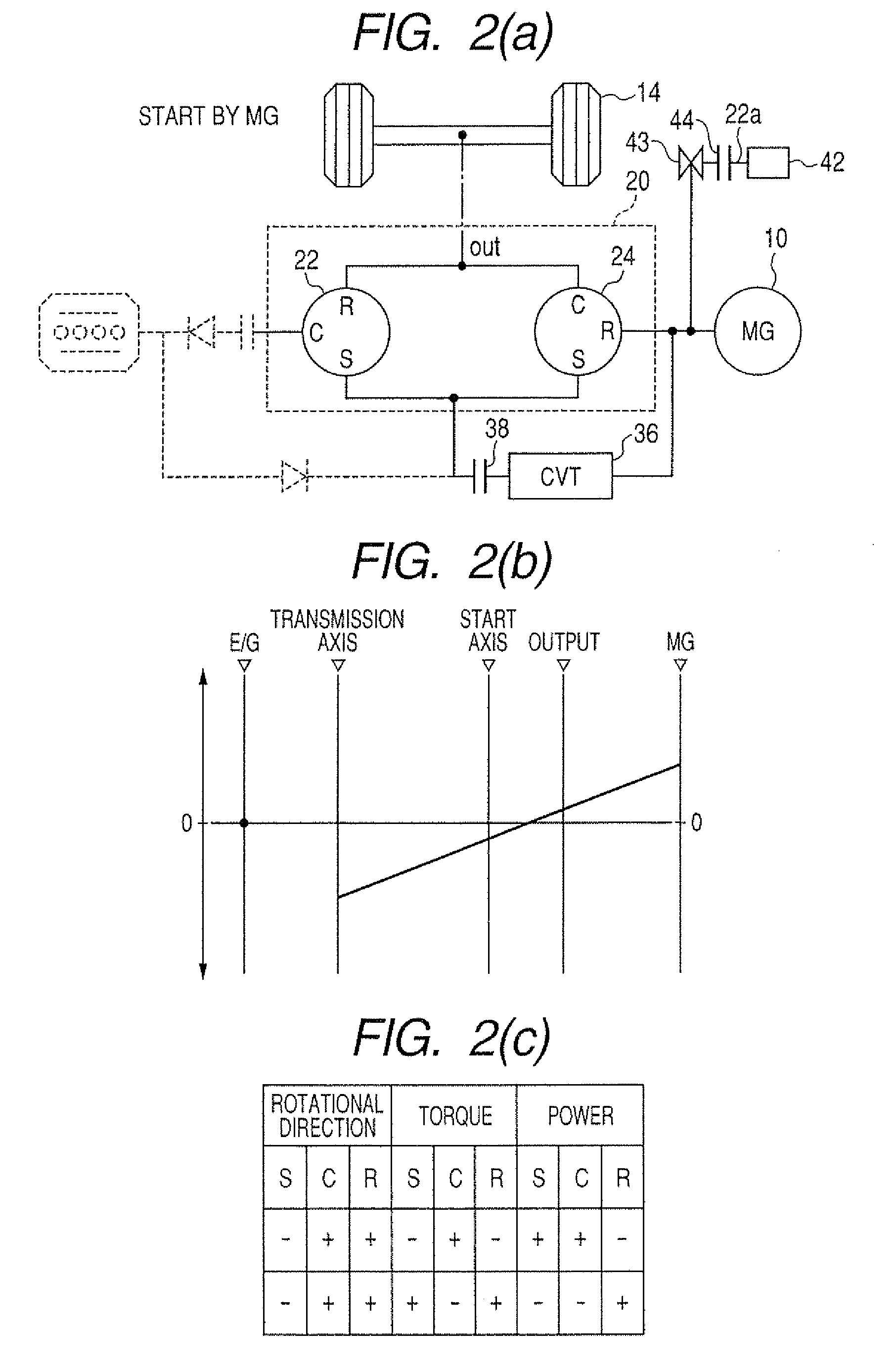
[0123]FIG. 7 illustrates a hybrid system according to the invention. The same reference numbers as employed in FIG. 1 refer to the same parts, and explanation thereof in detail will be omitted here.

[0124]The driven shaft 42a of the compressor 42 is coupled mechanically to the sun gears S of the first and second planetary gear sets 22 and 24. This permits rotors which are to rotate together with the sun gears S to be coupled to the driven shaft 42a through a pulley. The structure of this embodiment enables the torque of the sun gears S of the first and second planetary gear sets 22 and 24 or the ring gear R of the second planetary gear set 24 to be transmitted to the driven shaft 42a of the compressor 42.

third embodiment

[0125]FIG. 8 illustrates a hybrid system according to the invention. The same reference numbers as employed in FIG. 1 refer to the same parts, and explanation thereof in detail will be omitted here.

[0126]The driven shaft 42a of the compressor 42 is coupled mechanically between the clutch38 and the CVT 36. When the clutch 38 is engaged, the driven shaft 42a is connected to the sun gears S of the first and second planetary gear sets 22 and 24. Alternatively, when the clutch 38 is disengaged, the driven shaft 42a is connected only to the ring gear R of the second planetary gear set 24 and the motor-generator 10. This enables the power to be supplied to the compressor 42 when the vehicle is at a stop.

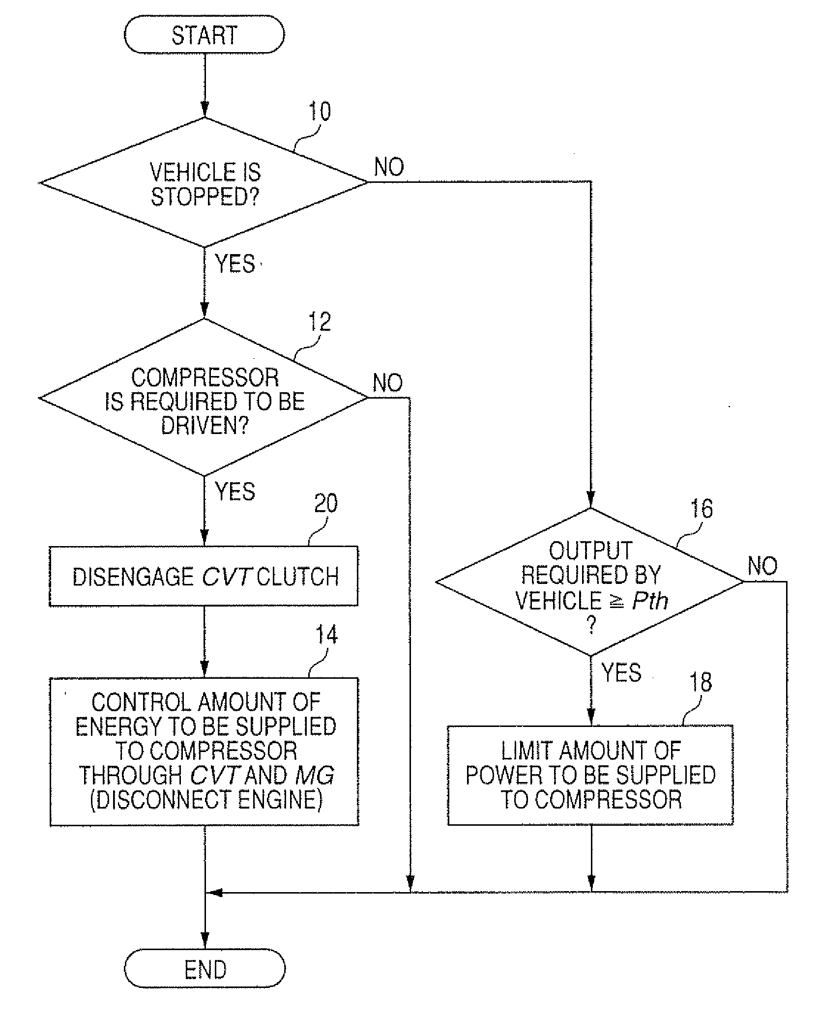
[0127]FIG. 9 is a flowchart of a sequence of logical steps or program to be executed by the controller 50 at a given time interval to control the amount of power to be supplied to the compressor 42 in the third embodiment. The same step number as employed in FIG. 5 represents the same opera...


PUM


Abstract

An in-vehicle power transmission apparatus is equipped with a motor-generator working as an engine to drive a vehicle and a power split device made up of a plurality of power split rotors. A first one of the rotors is coupled to a driven wheel of the vehicle, while a second one of the rotors is coupled to an accessory such as an air compressor of an air conditioner. The speed of the second rotor is controllable independently of that of the driven wheel. This eases restrictions on the supply of power produced by the generator-motor to the accessory. Alternatively, the rotors are so linked that when the speed of the first rotor is not zero (0), the speed of the second rotor has one of zero (0) and a value other than zero (0), thus ensuring the stability in supplying the power to drive the vehicle to the accessory.

Description

CROSS REFERENCE TO RELATED DOCUMENT[0001]The present application claims the benefits of priority of Japanese Patent Application Nos. 2009-108710 and 2009-108711 both filed on Apr. 28, 2009, disclosures of which are incorporated herein by reference.BACKGROUND OF THE INVENTION[0002]1 Technical Field of the Invention[0003]The present invention relates generally to an in-vehicle power transmission device equipped with three or more power split rotors which work to split power or torque among an electric rotating machine (e.g., a dynamo-electric machine), a driven-wheel of a vehicle, and an accessory mounted in the vehicle and are designed to rotate in conjunction with each other, and a power control system for a vehicle equipped with such a power transmission device.[0004]2 Background Art[0005]In recent years, in terms of reducing the amount of energy consumed by automotive vehicles, so-called hybrid vehicles have been put into practical use which are equipped with a rotary electric dri...

Claims


Application Information

Patent Timeline
IPC IPC(8): H02P17/00B60K25/00
CPCY02T10/6221Y10T477/347B60K25/00B60K6/48B60H1/004F16H2037/104F16H37/0846B60H1/3222F16H2037/102Y02T10/62
Inventor KAWASAKI, KOJIMATSUE, TAKENORITOKUDOME, YUJIINAGAKI, MITSUOOGAWA, OYUKI
Owner NIPPON SOKEN
Why Eureka
Try Eureka