Biomass gasification/pyrolysis system and process

a gasification/pyrolysis and biomass technology, applied in the field of conversion of organic lignocellulosic materials, can solve the problems of complex technology, poor quality products, and difficulty in maintaining desired heat transfer rates

Inactive Publication Date: 2010-11-04
INDIANA UNIV RES & TECH CORP
View PDF2 Cites 32 Cited by
  • Summary
  • Abstract
  • Description
  • Claims
  • Application Information

AI Technical Summary

Benefits of technology

[0009]The present invention provides a system and process capable of efficient production of syngas f...

Problems solved by technology

For example, partial combustion results in poor-quality products, for example, a syngas having an energy content of 150 BTU/ft3 or less, because of the dilution of the fuel gasses by the nitrogen in the injected air and the gaseous products of the combustion.
For indirect heat transfer, it can be difficult to maintain desired heat transfer rates because the process deposits coatings on the heat transfer surfaces that act as insulating materials.
Finally, direct heat transfer with circulating solids is effective but requires complex technology because the circul...

Method used


Image

  • Biomass gasification/pyrolysis system and process
  • Biomass gasification/pyrolysis system and process

Examples


Embodiment Construction

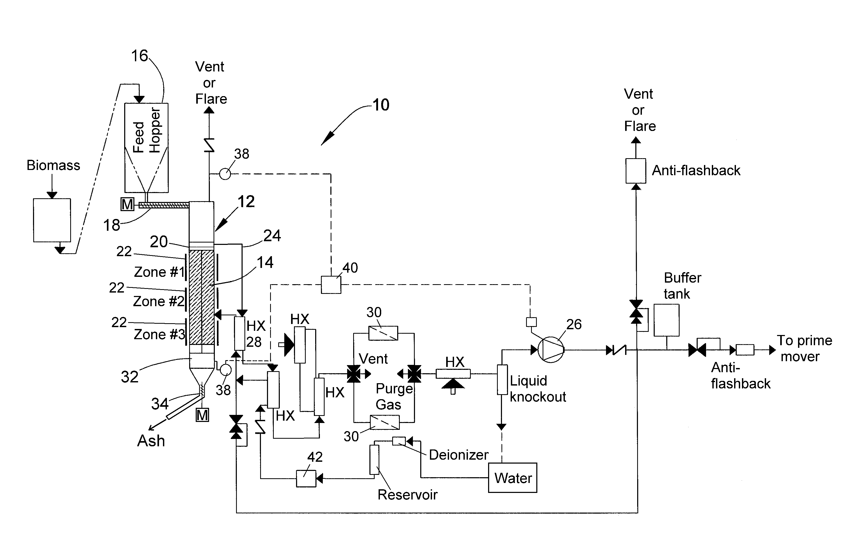
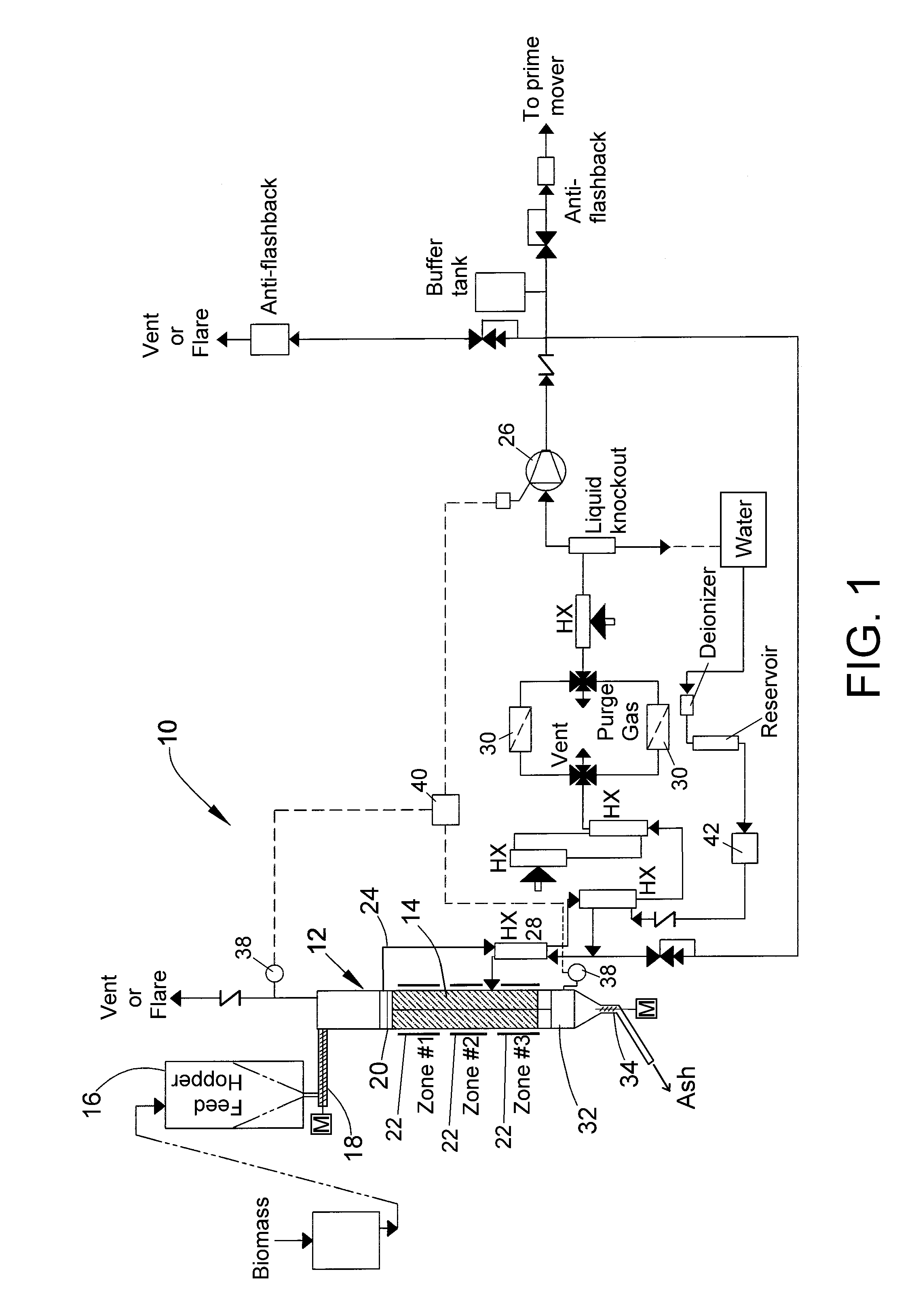
[0014]FIG. 1 schematically represents a biomass gasifier system 10 in accordance with an embodiment of the invention. The system 10 is configured to have a neutral atmospheric pressure reactor 12, whose configuration is capable of minimizing energy input and equipment complexity of the system 10. FIG. 1 represents a biomass material as being delivered to the reactor 12 from a bulk hopper 16 via a feeder device 18, represented in FIG. 1 as an auger powered by a motor (M), though other methods of delivery are also within the scope of the invention, such as through the use of a ram or by gravity feed only. The biomass material enters a reactor tube 14 within the reactor 12 through an entrance or throat 20 at an upper end of the tube 14. The tube 14 serves as the containment vessel and defines an internal passage within which the gasification process occurs, producing syngas as a desired product and dry ash as a byproduct. The reactor 12 is configured such that syngas flows out, as does...


PUM


Abstract

A system and process capable of promoting the energy content of a syngas produced from a biomass material. The system and process entail compacting a loose biomass material and simultaneously introducing the compacted biomass material into an entrance of a reactor tube, and then heating the compacted biomass material within the tube to a temperature at which organic molecules within the biomass material break down to form ash and a fuel gas mixture. The fuel gas mixture is withdrawn from the tube and the ash is removed from the tube through an exit thereof. The entrance and exit of the tube, the compaction step, and the removal step cooperate to inhibit ingress of air into the tube by forming a plug of the biomass material at the entrance of the tube and a plug of ash at the exit of the tube.

Description

CROSS REFERENCE TO RELATED APPLICATIONS[0001]This application claims the benefit of U.S. Provisional Application No. 61 / 270,393, filed Jul. 8, 2009, and is a continuation-in-part patent application of co-pending U.S. patent application Ser. No. 12 / 760,241, filed Apr. 14, 2010, which claims the benefit of U.S. Provisional Application No. 61 / 212,624, filed Apr. 14, 2009. The contents of these prior patent applications are incorporated herein by reference.BACKGROUND OF THE INVENTION[0002]The present invention generally relates to the conversion of organic lignocellulosic materials (biomass) into useful fuels (biofuels), and more particularly to a system and process capable of continuous conversion of biomass into synthesis gas (syngas).[0003]Syngas is a gas mixture containing carbon monoxide (CO) and hydrogen gas (H2) produced by the conversion of carbonaceous materials, such as coal, petroleum, and biomass materials. Though having a lower energy density than natural gas, syngas is sui...

Claims


Application Information

Patent Timeline
IPC IPC(8): C10J3/02C10J3/72C10J3/30
CPCY02E50/32C10J3/08C10K1/024C10B53/02C10J2300/0916C10J2300/0976C10J2300/1269C10J2300/1276C10J2300/1646C10J2300/1693C10J2300/1853C10J2300/1884C10J2300/1892C10J2200/158C10B57/16Y02E50/14C10J3/20Y02P20/145Y02E50/30Y02E50/10C10J3/34C10J3/723C10J2200/15
Inventor PAGANESSI, JOSEPH E.SCHUBERT, PETER J.WILKS, ALAN D.
Owner INDIANA UNIV RES & TECH CORP
Why Eureka
Try Eureka