Compact, flexible csp installation for continuous, semi-continuous and batch operation

Inactive Publication Date: 2010-11-04
SMS DEMAG AG
View PDF27 Cites 31 Cited by
  • Summary
  • Abstract
  • Description
  • Claims
  • Application Information

AI Technical Summary

Benefits of technology

[0013]Furthermore, it is advantageous if the coil store is designed to receive two, three or more coils.

Problems solved by technology

These installations have the disadvantage that they can either be operated in discontinuous operation or only in continuous operation.
With a changeover of rolls, in the case of a continuous operation it is no longer possible to maintain the operation.
In the case of a disconti

Method used


Image

  • Compact, flexible csp installation for continuous, semi-continuous and batch operation
  • Compact, flexible csp installation for continuous, semi-continuous and batch operation
  • Compact, flexible csp installation for continuous, semi-continuous and batch operation

Examples


Example

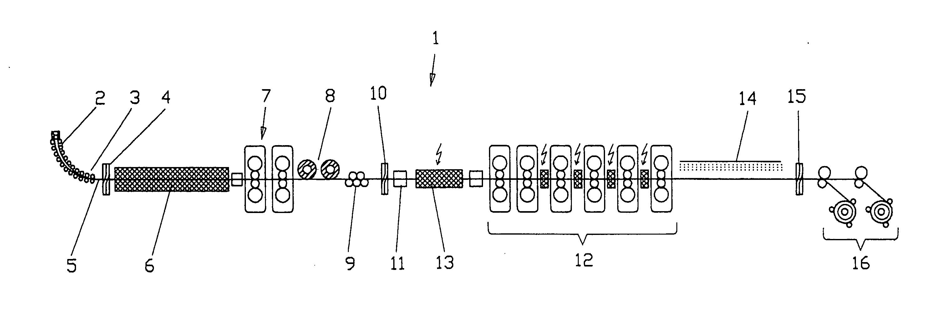
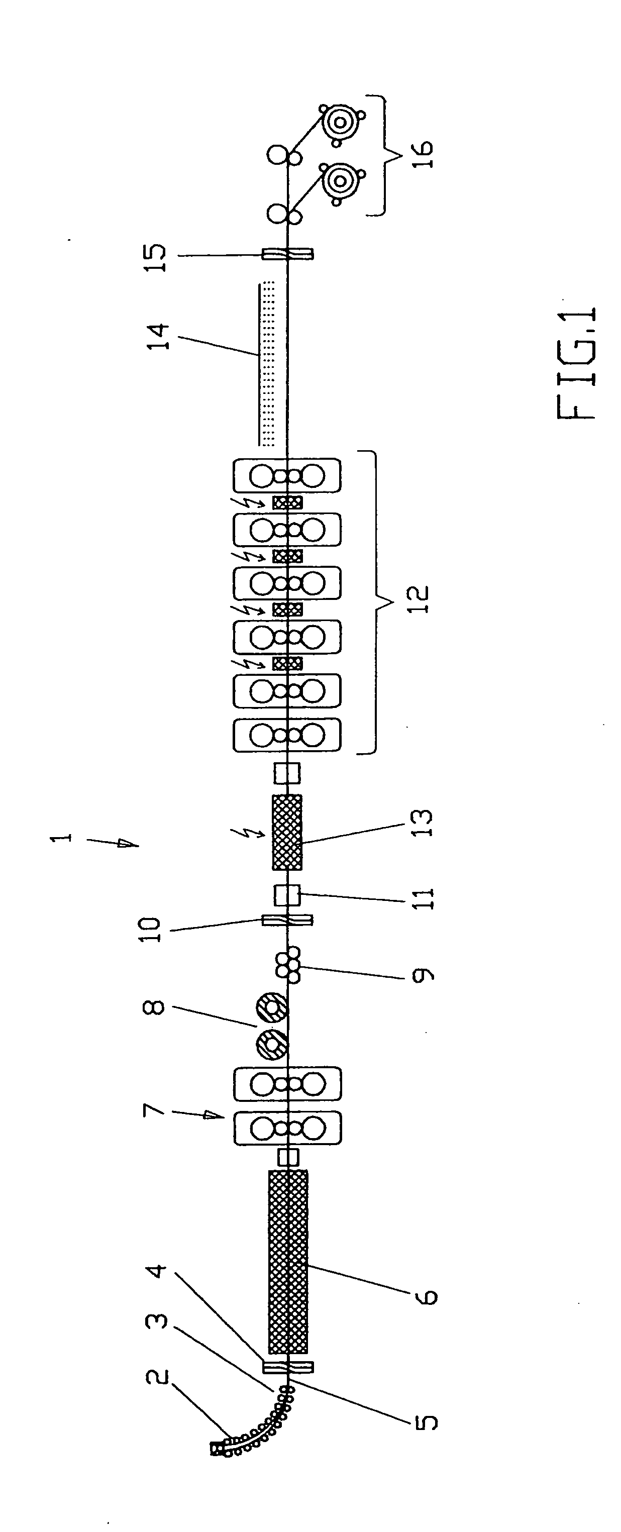
[0029]FIG. 1 shows a diagrammatic illustration of a compact, flexible CSP installation 1 for endless, semi-endless and batch operation. The installation 1 has here a casting machine 2 with a caster outlet 3. After the caster outlet 3, a cutter 4 is provided, in order to be able to cut the strand 5 emerging out from the caster outlet 3. After the cutter 4, a furnace 6 is provided, such as preferably a tunnel furnace, which heats the strand 5 up to the desired temperature. The furnace 6 is therefore arranged between the caster outlet 3 and the cutter 4 on the one hand and the subsequent roughing stand group 7 on the other hand. In the example embodiment of FIG. 1, the roughing stand group 7 has two roughing stands. However, according to another idea in accordance with the invention, the roughing stand group 7 may also have one or three roughing stands. In this example embodiment, after the roughing stand group 7 a so-called coil store 8 is provided for the strand material, in order to...


PUM

PropertyMeasurementUnit
Temperatureaaaaaaaaaa
Lengthaaaaaaaaaa
Thermal propertiesaaaaaaaaaa

Abstract

The invention relates to a compact, flexible CSP installation (1,101,201,301,401) for endless, semi-endless and batch operation with a casting machine, a roughing stand group (7,111,211) and a finishing stand group (12,118,218), wherein for the batch operation or the semi-endless operation, a coil store (8,113,213,501) is integrated into the roll table, which stores the pre-strip or slab coming from the roughing stand, with the coil store being deactivated in the case of endless operation. The coil store (8,113,213,501) is designed for an increased holding quantity of pre-strips or slabs such that two, three or more pre-strips or slabs can be wound to jumbo coils on a coil.

Description

TECHNICAL FIELD[0001]The invention relates to a compact, flexible CSP installation for endless, semi-endless and batch operation, as in particular in accordance with the introductory clause of claim 1.PRIOR ART[0002]In CSP installations (Continuous Strip Production), the strip is typically produced in a continuous process, as the name already suggests. This means that the casting process and the rolling process take place directly in succession from almost one heat.[0003]The DE 10 2006 054 932 A1 discloses a CSP installation in which both an induction furnace and a holding furnace are provided between the casting machine and the rolling train, in order to keep the thin slab to temperature or to increase the temperature slightly, in which both the holding furnace and also the induction furnace are activated, deactivated or respectively controlled or regulated depending on the type of operation.[0004]EP 0 286 862 A1 discloses an endless rolling, in which the casting and the rolling pr...

Claims


Application Information

Patent Timeline
IPC IPC(8): B21B3/00
CPCB21B1/46B21B1/463B21B1/466B21B13/22B21B2015/0064B21B39/084B21B45/004B21B45/008B21B2015/0057B21B39/006Y02P70/10
Inventor SEIDEL, JURGENSUDAU, PETERHOF, HARTMUTPETERS, MATTHIAS
Owner SMS DEMAG AG
Why Eureka
Try Eureka