Static fluid mixer

Inactive Publication Date: 2010-11-04
MG GROW UP CORP +1
View PDF54 Cites 28 Cited by
  • Summary
  • Abstract
  • Description
  • Claims
  • Application Information

AI Technical Summary

Benefits of technology

[0032]In a static flow mixer according to the present invention, a fluid component can be miniaturized more finely and uniformized (ultra-miniaturized and uniformized). Moreover, in the present invention, when a fluid having passed through a mixing flow path is allowed to flow out from a flow outlet to a collecting flow path, a trailer opening of an annular outflow path opening in a ring at substantially equal intervals all over an entire circumference is formed as a flow outlet; the flow outlet thus exists at substantially equal width all over the entire circumference; and the flow line of the fluid flowing out substantially equally from the entire circumference of the flow outlet is not extremely disturbed. Therefore, variation in fluid pressure is not prone to occur. As a result, the fluid pressure is uniformized, and a flow path resistance lowers. If the flow path resistance lowers, a pressure loss is reduced, and even if a pressure of the fluid to be supplied is not set at a high pressure, a treatment quantity can be increased.
[0033]In addition, a flow path forming space communicating with an annular outflow path is formed of mixing units adjacent to each other and a casing main body; in the flow path forming space, the fluid having passed through a mixing flow path is flown out from an entire circumference of a flow outlet opening in a ring shape at a substantially equal width into a diameter-extended flow path forming

Problems solved by technology

Incidentally, in the conventional static fluid mixer, the fluid having passed through the mixing flow path flows into a plenty of small-diameter circular holes which are flow outlets formed at the second mixing element in a diverting manner; a pressure of the fluid passing through each of the small-diameter circular holes becomes non-uniform; therefore, the flow line greatly disturbs and a pressure loss increases, making it difficult to increase a treatment quantity per

Method used


Image

  • Static fluid mixer
  • Static fluid mixer
  • Static fluid mixer

Examples


first embodiment

[Static Fluid Mixer of First Embodiment]

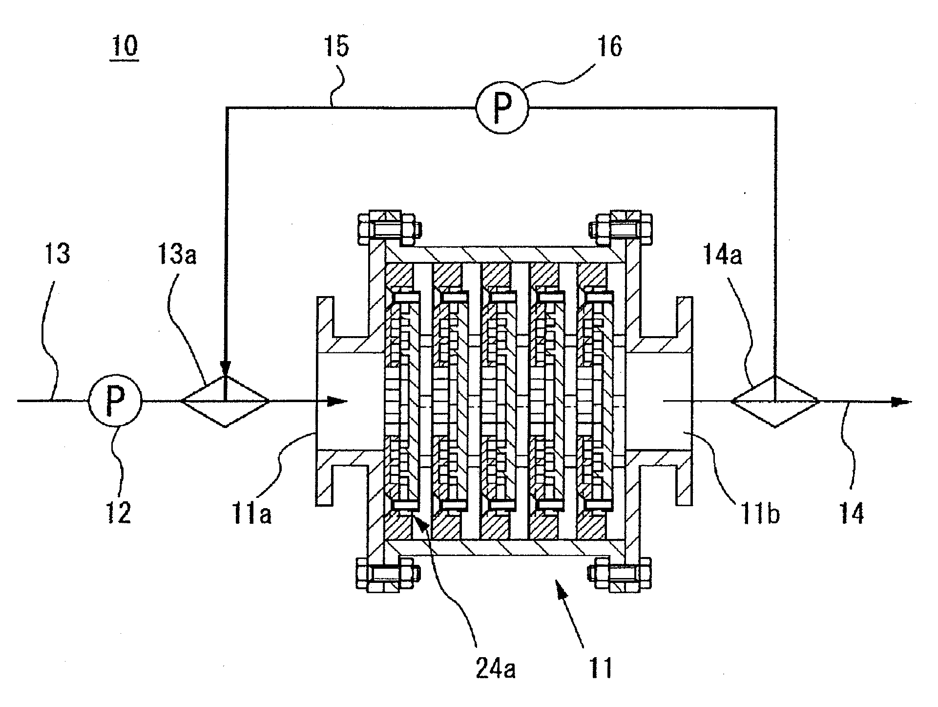
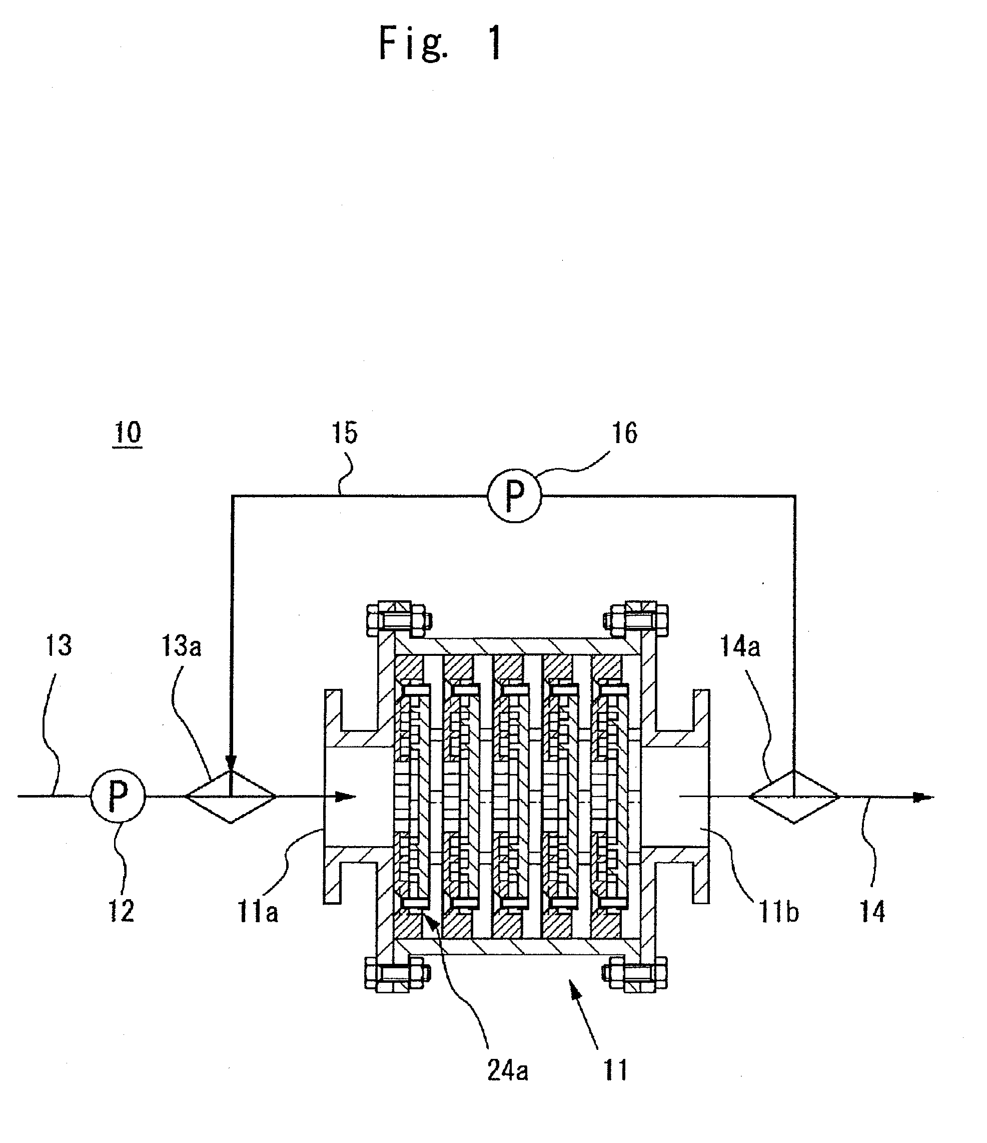
[0132]First, a static fluid mixer of a first embodiment will be described in detail, referring to FIGS. 1 to 8.

[0133]As shown in FIG. 1, a static fluid mixer 10 of the first embodiment is provided with: a fluid mixer 11 for applying mixing treatment to fluid targeted for treatment; a fluid introducing pipe 13 connected to a fluid introducing port 11a of the fluid mixer 11; and a fluid lead-out pipe 14 connected to a fluid lead-out port 11b of the fluid mixer 11. In addition, a first pump 12 for supplying treatment fluid to the fluid mixer 11 is provided partway of the fluid introducing pipe 13. In this manner, the fluid is introduced into the fluid mixer 11 through the fluid introducing pipe 13 by means of the first pump 12 so as to be able to apply mixing treatment by means of the fluid mixer 11. In addition, the fluid to which mixture treatment has been applied can be led out from the fluid lead-out pipe 14.

[0134]In addition, one end of a fl...

second embodiment

[Static Fluid Mixer of Second Embodiment]

[0175]Next, a static fluid mixer 10 A of a second embodiment will be described in detail, referring to FIGS. 9 to 13.

[0176]Unlike the mixing unit 24 of the first embodiment, a fluid mixer 11A of a static fluid mixer 10A of the second embodiment has guide members 52 at a collecting flow path 26 through which the fluid having flown out from an annular outflow path 24a of the mixing unit 24A flows (see FIG. 11). Like constituent elements of the static fluid mixer 10 of the first embodiment are designated by like reference numerals, and a duplicate description thereof is omitted.

[0177]As shown in FIG. 9, the mixing unit 24A of the fluid mixer 11A of the embodiment is provided with a collecting-flow-path forming element 50 which comprises a guide member 52 which is a member of stabilizing a flow-path sectional area of the collecting flow path 26, in addition to the first mixing element 30 and the second mixing element 40.

[0178]Among them, the seco...

third embodiment

[Static Fluid Mixer of Third Embodiment]

[0201]Next, a static flow mixer 10B of a third embodiment will be described referring to FIGS. 15-18. Like constituent elements of the static fluid mixer 10A of the second embodiment are designated by like reference numerals, and a duplicate description thereof is omitted here.

[0202]Unlike the fluid mixer 11A of the second embodiment, a fluid mixer 11B of the static fluid mixer 10B of the third embodiment is provided with a lead-out side element 60 which is disposed in opposite to the collecting-flow-path forming element 50, as a constituent element of the mixing unit installed in the casing main body 21.

[0203]Specifically, as shown in FIG. 16, a mixing unit 24B of the fluid mixer 11B of the third embodiment is provided with: the lead-out side element 60 in addition to the first mixing element 30, the second mixing element 40, and the collecting-flow-path forming element 50, of the second embodiment.

[0204]The first and second mixing elements 3...


PUM

PropertyMeasurementUnit
Pressureaaaaaaaaaa
Flow rateaaaaaaaaaa
Shapeaaaaaaaaaa

Abstract

A static fluid mixer which can perform processing such as generation of ultrafine uniform bubbles and has small pressure loss. A static fluid mixer has mixing units having outflow openings for allowing fluid having passed through mixing flow paths to flow through the outflow openings. The mixing units are arranged in a tubular casing body at intervals in the axis direction of the casing body. Adjacent mixing units and the casing body forma flow path forming space. Each mixing unit has an annular outflow path communicating with the end of each mixing flow path. The annular outflow path is open in a ring-like form having a substantially constant width along the entire circumference. The opening at the end of the annular outflow path functions as an outflow opening connecting to the flow path forming space. In the outflow path forming space is formed a collection flow path into which liquid having passed through the mixing flow path collects after flowing from the entire circumference of the outflow opening which is open in the ring-like form and moving toward the axis of the casing body.

Description

TECHNICAL FIELD[0001]The present invention relates to a static fluid mixer which is capable of ultra-finely and uniformly mixing fluids, for example, a liquid and a liquid; a liquid and a gas such as oxygen or a liquid targeted to be reformed such as water; a liquid and an aqueous fluid such as a royal jelly; and a solid such as a see weed and a liquid.BACKGROUND ART[0002]Conventionally, one aspect of a static fluid mixer includes the one in which: a disk-shaped second mixing element is disposed to be opposed to a disk-shaped first mixing element forming a flow inlet of fluid at a center part thereof; and between the mixing elements, a mixing flow path is formed through which the fluid having flown from the flow inlet to between both the mixing elements flows. In addition, the mixing flow path is provided with: a plurality of diverting parts adapted to flow and divert the fluid having flown from the flow inlet in a radiation direction; and a plurality of converging parts adapted to ...

Claims


Application Information

Patent Timeline
IPC IPC(8): B01F3/04B01F5/06A23L21/20A23L35/00
CPCB01F5/0604B01F15/065C02F2303/26C02F1/685C02F1/006B01F25/422B01F35/92
Inventor MOGAMI, KENICHIKUMAZAWA, HIDEHIRO
Owner MG GROW UP CORP
Why Eureka
Try Eureka