Rotary table for permanent magnet rotating machine and method for manufacturing permanent magnet rotating machine

Active Publication Date: 2010-11-04
SHIN ETSU CHEM IND CO LTD
View PDF9 Cites 23 Cited by
  • Summary
  • Abstract
  • Description
  • Claims
  • Application Information

AI Technical Summary

Benefits of technology

[0015]By means of the present invention, a permanent magnet rotating machine can be manufactured so that a gap between rotors is held with high dimensional accuracy, with a force less than hit

Problems solved by technology

Thus, the density of magnetic flux that links with an armature coil increases, which results in a higher induced voltage.
Since this rotor radiates magnetic flux only from its circumferential surface, the interior space of the rotor is an electrically useless space.
As one of the reasons therefor, it h

Method used


Image

  • Rotary table for permanent magnet rotating machine and method for manufacturing permanent magnet rotating machine
  • Rotary table for permanent magnet rotating machine and method for manufacturing permanent magnet rotating machine
  • Rotary table for permanent magnet rotating machine and method for manufacturing permanent magnet rotating machine

Examples


Embodiment Construction

)

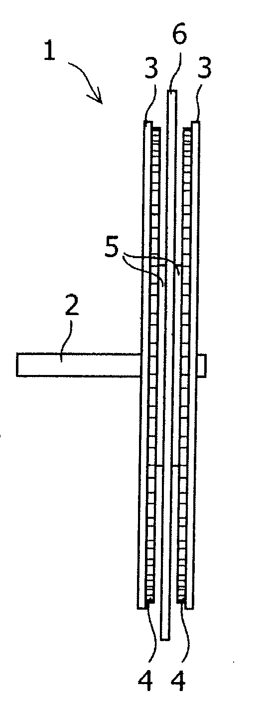
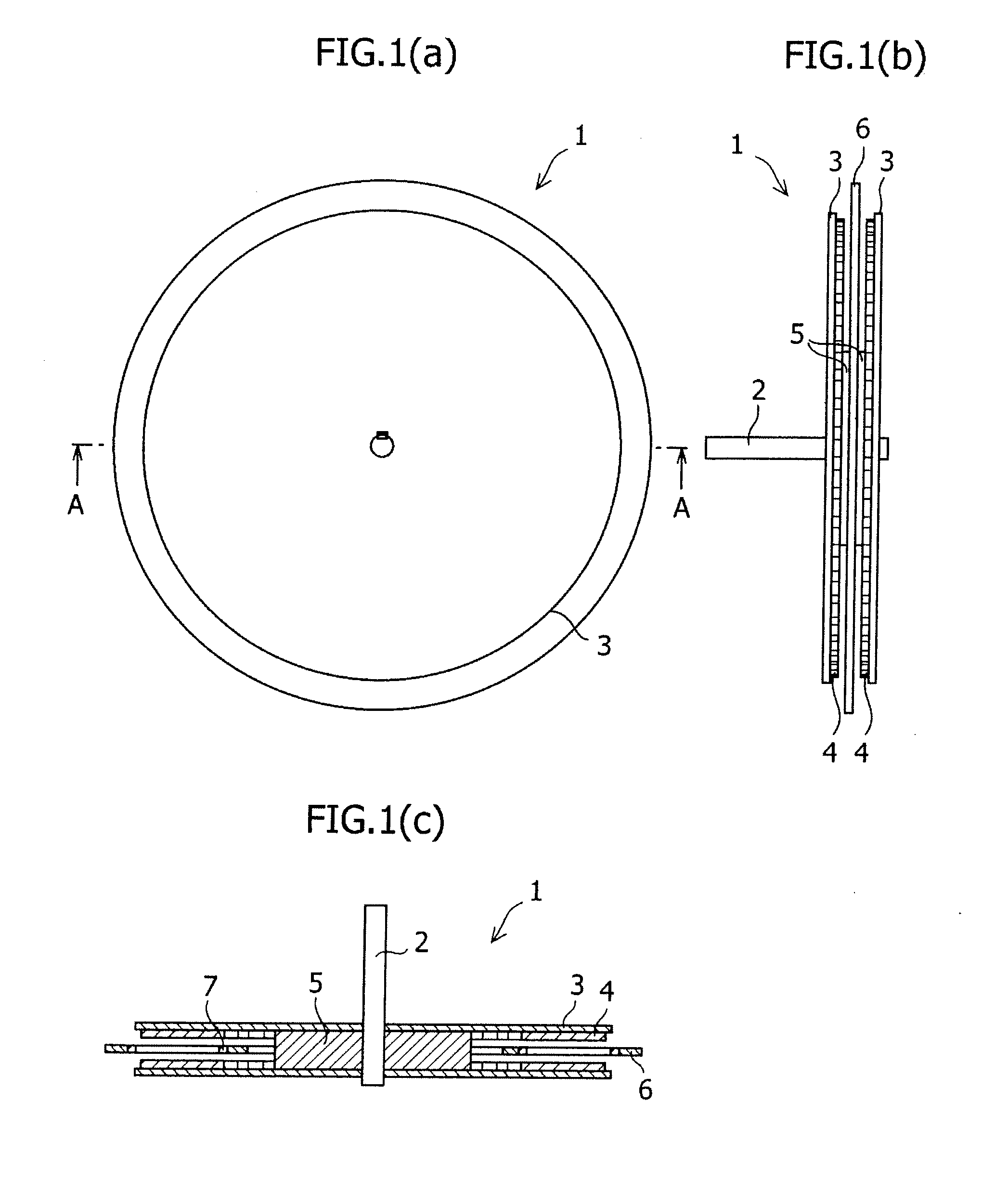
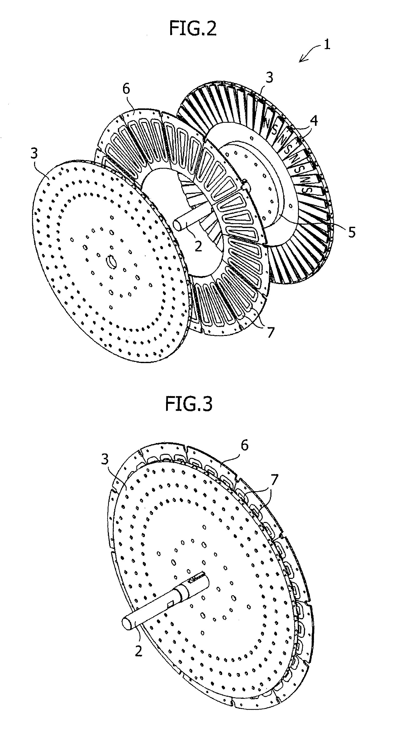
[0029]This invention is directed to a method of manufacturing an axial gap type permanent magnet rotating machine, especially for providing a rotary table for a permanent magnet rotating machine, with which a larger permanent magnet rotating machine can be assembled with a less force than hitherto, and for providing a method for assembling the same.

[0030]As the physical size of axial gap type permanent magnet rotating machines increase, the number and physical size of magnets used therein increase.

[0031]With a method for mounting magnets to a rotor in which, for example, as shown in FIG. 10, each magnet is moved perpendicularly towards the face of a rotary table from above of the rotary table, it is required to move the magnet close to the rotary table while maintaining the state where the bottom surface of the magnet is parallel to the top surface of the rotary table. When a large magnetic poles are used, it is necessary that a single magnetic pole is constituted by two or more ma...


PUM

PropertyMeasurementUnit
Polarityaaaaaaaaaa
Widthaaaaaaaaaa

Abstract

A method for assembling rotors which is applicable to a large axial gap type permanent magnet rotating machine is provided.
A permanent magnet rotating machine comprising: a rotating shaft; at least two rotors comprising a table-like structure and permanent magnets attached thereto, the table-like structures being connected to the rotating shaft and being disposed in an axial direction of the rotating shaft; and a stator comprising a table-like structure and stator coils around which a copper wire is wound, said stator being disposed in a gap formed by the rotors so that the stator being separated from the rotating shaft, is manufactured by the following steps of: assembling the two rotors such that a predetermined gap is formed therebetween; and mounting the magnets on the table-like structures by inserting the magnet from the radially outer side of the table-like structures towards the center of the rotation with the assembled state being maintained.

Description

BACKGROUND OF THE INVENTION[0001]1. Field of the Invention[0002]The present invention relates to a permanent magnet rotating machine available for motors and generators, and more specifically to an axial gap type permanent magnet rotating machine in which rotors and a stator are arranged in the direction along a rotating shaft so that the rotors are oppositely disposed with the stator being interposed therebetween.[0003]2. Description of the Related Art[0004]There are various types of rotating machines used in a motor or a generator, including both a type that uses a permanent magnet as a magnetic field system and a type that uses a coil as a magnetic field system. While each type has its advantages and disadvantages, a permanent magnet rotating machine that uses a permanent magnet as a magnetic field system is generally employed when electric generation efficiency is important. This is because, when both types of the magnet rotating machines having the substantially same physical s...

Claims


Application Information

Patent Timeline
IPC IPC(8): H02K1/30H02K15/03
CPCH02K1/2793H02K15/03Y10T29/49009Y10T29/49012H02K21/24H02K1/2798H02K15/125H02K1/28H02K16/02H01F13/003
Inventor DOI, YUHITOKOBAYASHI, HIDEKIMINOWA, TAKEHISAMIYATA, KOJIMIYATA, MINORIMIYATA, ATSUSHI
Owner SHIN ETSU CHEM IND CO LTD
Why Eureka
Try Eureka