
Fluorescent lamp with uv-blocking layer and protective sleeve

a technology of uv blockage and fluorescent lamps, which is applied in the direction of discharge tubes/lamp details, discharge tubes luminescnet screens, low-pressure discharge lamps, etc., can solve the problems of coating and sleeves being subject to degradation, fluorescent lamps are susceptible to breaking, coatings and sleeves to develop yellowing or haz

Inactive Publication Date: 2010-11-04
GENERAL ELECTRIC CO
View PDF34 Cites 6 Cited by
  • Summary
  • Abstract
  • Description
  • Claims
  • Application Information

AI Technical Summary

Problems solved by technology

Fluorescent lamps are susceptible to breaking if dropped or bumped.
Often, these coatings and sleeves are subject to degradation from UV-light emitted from the fluorescent lamp.
Such degradation causes the coatings and sleeves to develop yellowing or haze that partially blocks transmission of visible light.
Moreover, such degradation causes the coatings and sleeves to become more brittle over time, so that they are less able to provide impact resistance and act as containment envelopes.

Method used


Image

  • Fluorescent lamp with uv-blocking layer and protective sleeve
  • Fluorescent lamp with uv-blocking layer and protective sleeve

Examples


example 1

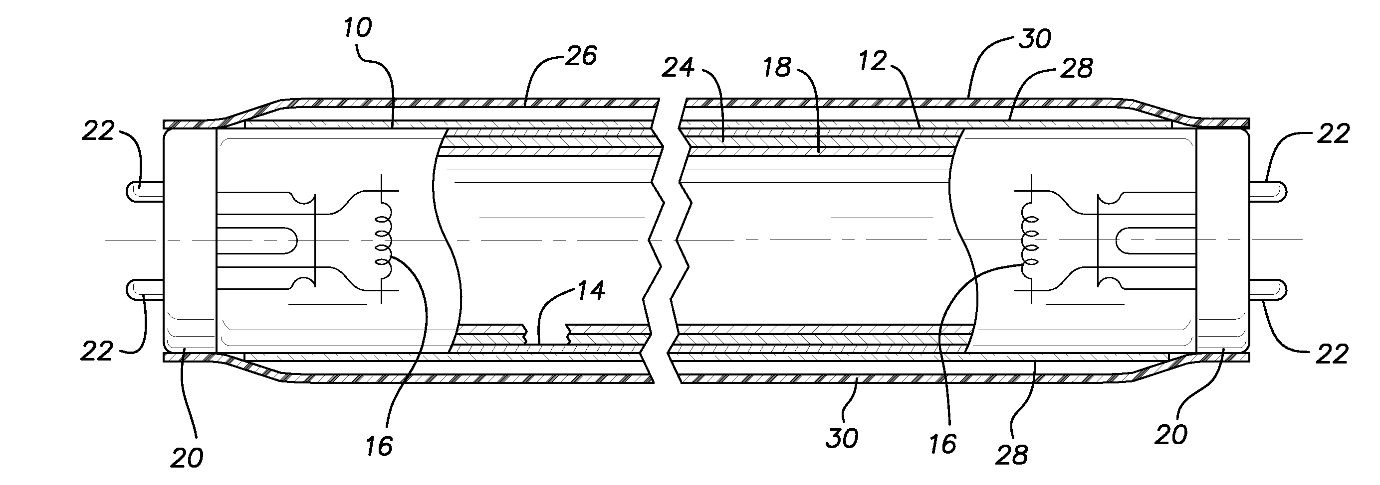
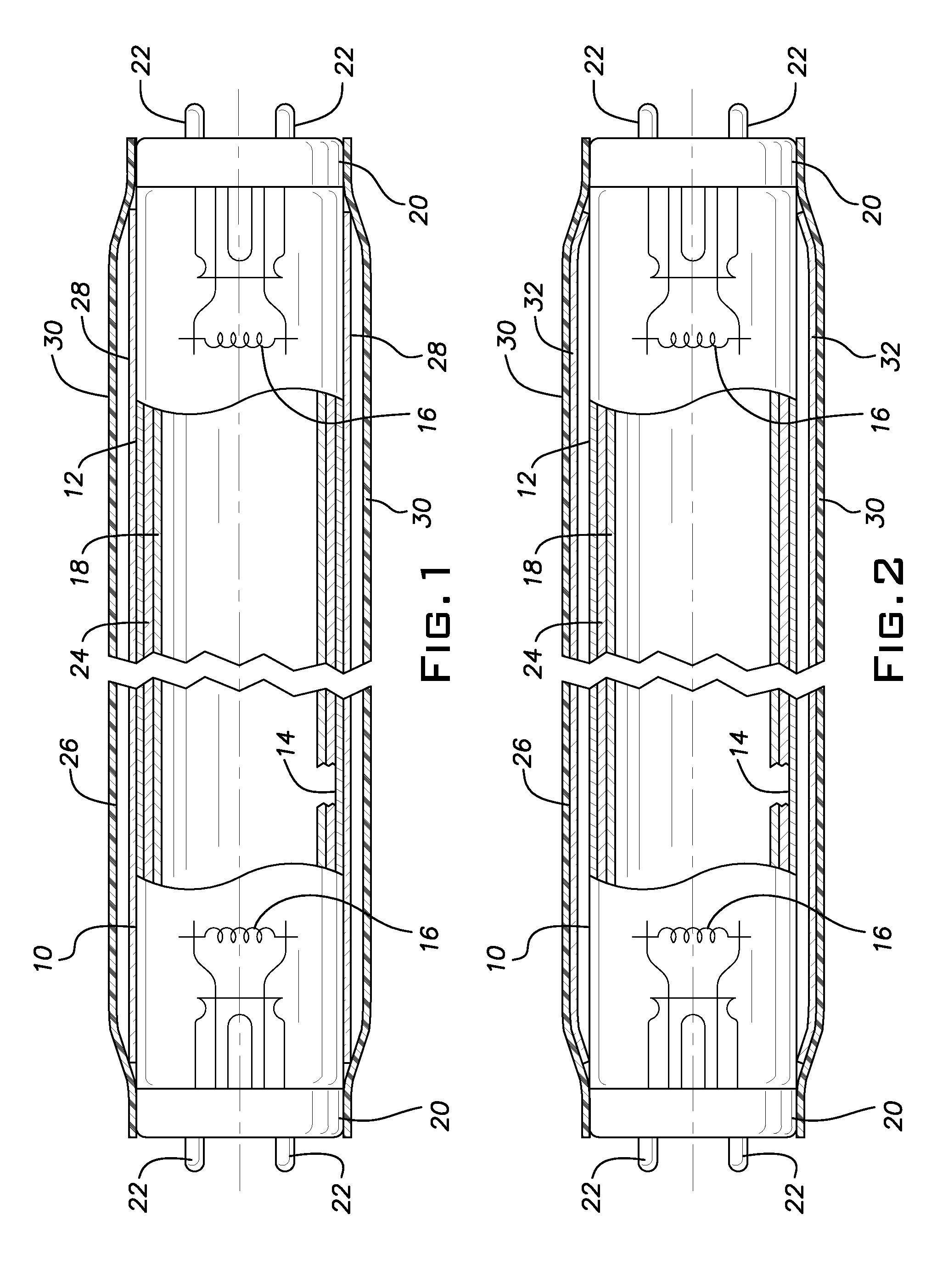
[0019]Two layers were tested for irradiance: 1. A conventional four foot linear fluorescent lamp (F32T8 / SPX30) was coated on its outer surface with about 8 g of GUZ-140 from Nippan Kenkyujo (“Coated Lamp”). 2. A lamp the same as the Coated Lamp, but without the coating (“Bare Lamp”). Irradiance was measured with an Optronics Laboratories OL756 double monochromator calibrated with NIST traceable standards. The detector was placed 20 cm from the center of the lamp. The lamps were burned horizontally and run with reference photometry at line volts. The irradiance data for the Coated Lamp and Bare Lamp is given in Table 1. As can be seen, the coating was very effective in blocking UV radiation. The invented layers 28, 32 preferably permit not more than 5, 10 or 20 percent transmission at 300, 330, 350, 360, 380 and 390 nm after 50 hours of operation.

TABLE 1WavelengthIrradiance of BareIrradiance of Coated(nm)Lamp W / cm2Lamp W / cm22882.02E−105.76E−122901.28E−104.06E−122923.54E−105.47E−12294...


PUM


Abstract

A fluorescent lamp having a protective polymeric sleeve to provide impact resistance and contain fragments if the lamp shatters. A UV-blocking layer is coated on the outside of the glass envelope of the lamp or on the inside of the sleeve to help protect the polymeric sleeve from UV degradation. The UV-blocking layer includes a UV-blocking component of Al2O3 or ZnO or SiO2 or TiO2 or mixtures thereof.

Description

BACKGROUND OF THE INVENTION[0001]1. Field of the Invention[0002]The present invention is directed to a fluorescent lamp with a UV-blocking layer which protects a protective polymeric sleeve surrounding the lamp.[0003]2. Description of Related Art[0004]Fluorescent lamps are susceptible to breaking if dropped or bumped. Coatings and sleeves have been developed for fluorescent lamps which have two functions: 1) to absorb impacts and thus impart increased impact resistance to the lamp, to reduce breakage, and 2) to act as a containment envelope to contain shards or fragments of glass in case the lamp shatters. Often, these coatings and sleeves are subject to degradation from UV-light emitted from the fluorescent lamp. Such degradation causes the coatings and sleeves to develop yellowing or haze that partially blocks transmission of visible light. Moreover, such degradation causes the coatings and sleeves to become more brittle over time, so that they are less able to provide impact resi...

Claims


Application Information

Patent Timeline
Patent Type & Authority Applications(United States)
IPC IPC(8): H01J1/62
CPCH01J61/34H01J61/72H01J61/35
Inventor KOSTKA, JAMES MICHAELJANSMA, JON B.
Owner GENERAL ELECTRIC CO
Learn More