Intrusion Detecting System With Polarization Dependent Sensing Elements

a polarization-dependent sensing element and intrusion detection technology, applied in the field of methods and systems for detecting disturbances, can solve the problems of complex system design, large capital investment, and constant threat of perimeter breaching by unwanted intruders,

Inactive Publication Date: 2010-11-04
CORNING INC
View PDF6 Cites 13 Cited by
  • Summary
  • Abstract
  • Description
  • Claims
  • Application Information

AI Technical Summary

Problems solved by technology

Sensitive sites such as nuclear power plants, water treatment systems, oil pipelines, and military facilities, are consistently under the threat of perimet

Method used


Image

  • Intrusion Detecting System With Polarization Dependent Sensing Elements
  • Intrusion Detecting System With Polarization Dependent Sensing Elements
  • Intrusion Detecting System With Polarization Dependent Sensing Elements

Examples


example 1

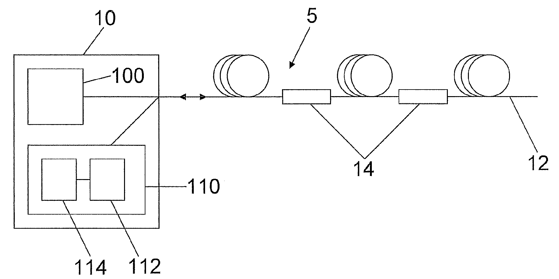
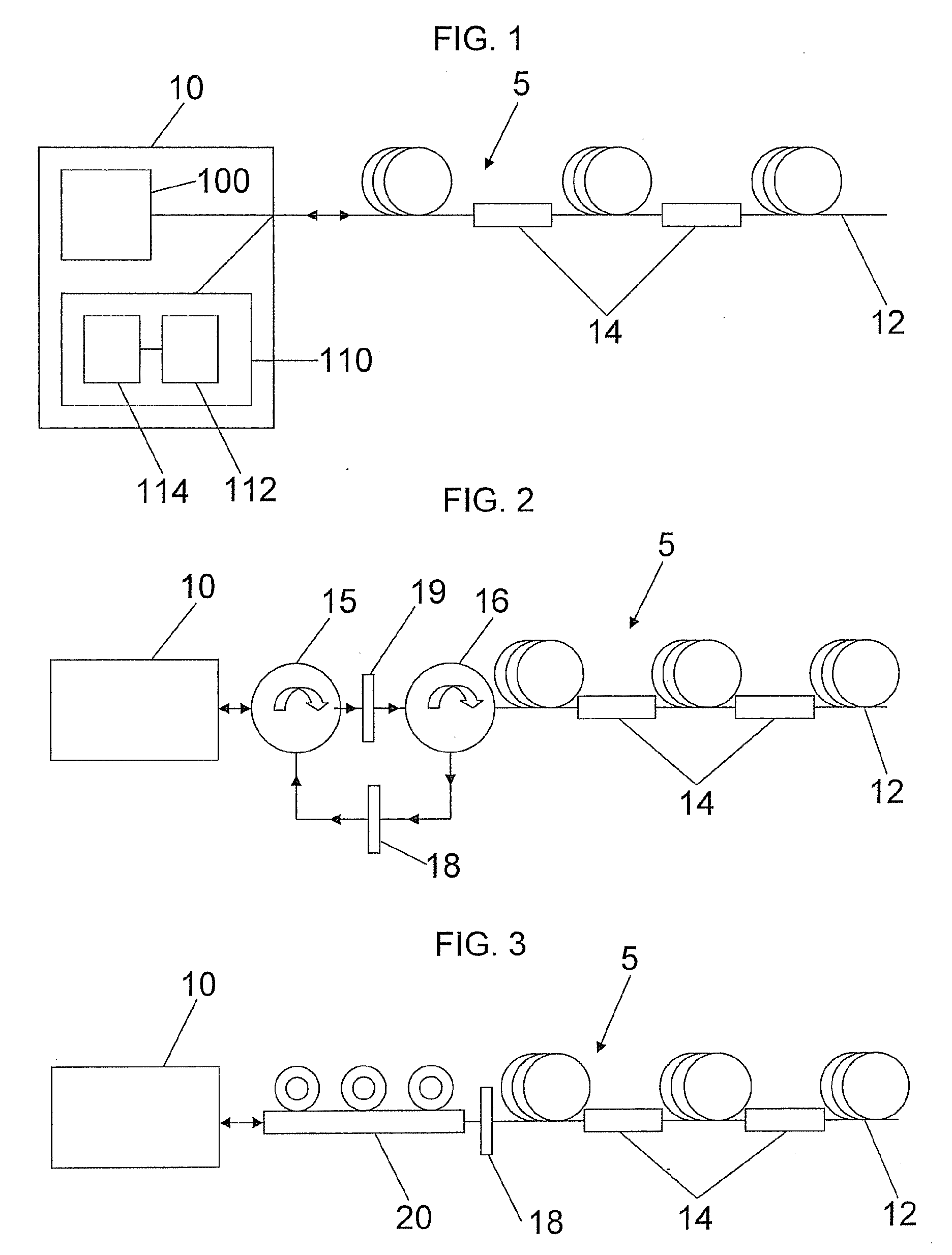
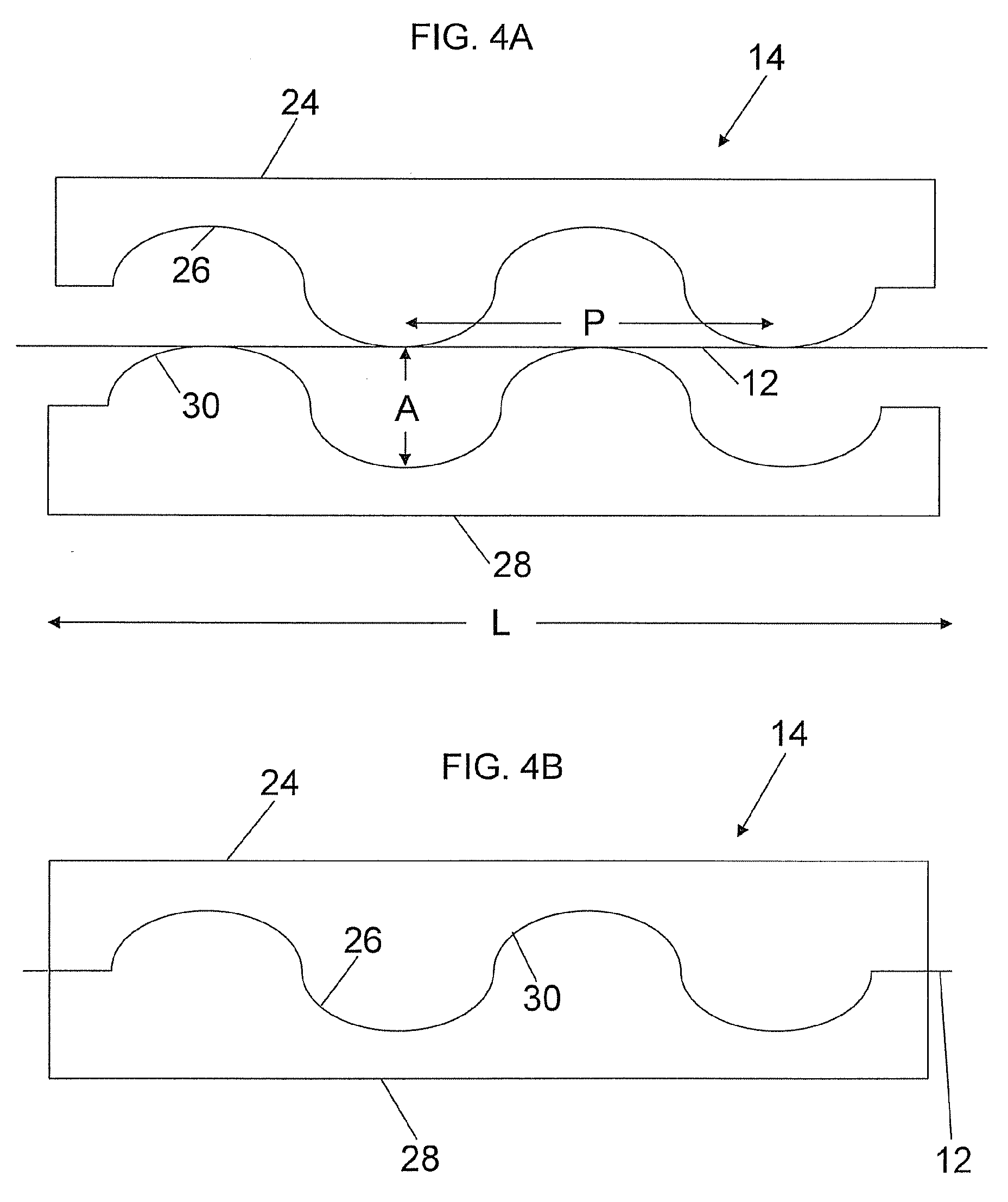
[0057]An HP 8147 OTDR outputting 10 ns pulses at a wavelength of 1550 nm, was used to launch optical pulses into an unjacketed single mode optical fiber having a length of 50 kilometers. At a distance of about 9.8 kilometers along the fiber, a paddle polarization controller with 3 paddles was used to simulate intrusion effects, followed by a microbending gear rack having a length of about 3 centimeters and opposing corrugated surfaces having a period of about 1 millimeter and an amplitude of about 400 μm. The microbending gear rack was mounted on a translation stage coupled to a load cell that allows determination as to the amount of force applied onto the fiber. The distance between the polarization controller and microbending gear rack was 20 meters. This same polarization controller and microbending gear rack configuration was repeated 80 meters beyond the first microbending gear rack. A LabView VI controlled the OTDR, compared new backscattered traces with stored background refe...

example 2

[0060]The experimental conditions set forth in Example 1 were repeated except instead of moving a paddle on the polarization controller nearer to the ODTR, a paddle on the polarization controller farther from the ODTR was moved. This movement also resulted in a polarization change of the incoming light, causing mode coupling to occur where the fiber was subjected to microbending, inducing a noticeable change in the RBS, allowing for pinpointing of the time and location of the disturbance. The resulting difference trace is shown in FIG. 9A and the resulting moving standard deviation and intrusion location A is shown in FIG. 9B.

example 3

[0061]The experimental conditions set forth in Examples 1 and 2 were repeated except both polarization controllers were removed and hardcover books were placed over a portion of the fiber between the microbending gear racks (i.e., at a distance of between about 9.82 and 9.9 kilometers along the fiber). The pressure of the weight of the books resulted in a polarization change of the incoming light, causing mode coupling to occur where the fiber was subjected to microbending, inducing a noticeable change in the RBS, allowing for pinpointing of the time and location of the disturbance. The resulting moving standard deviation of the difference trace is shown in FIG. 10. While the detected signal in this example is about an order of magnitude lower than in Examples 1 and 2, it was still well above the perturbation threshold of 0.008 a.u.


PUM


Abstract

A detection system includes a length of optical fiber and an OTDR coupled to the optical fiber. The OTDR includes a radiation source providing pulsed radiation to the fiber, a detector detecting radiation that is backscattered through the fiber, and a processor capable of analyzing the variation of the radiation that is backscattered through the fiber. At least two polarization dependent sensing elements are positioned along the length of optical fiber.

Description

FIELD OF THE INVENTION[0001]The present invention relates generally to a method and system for detecting a disturbance along the length of the fiber, and particularly to a method and system that utilizes Optical Time Domain Reflectometry (OTDR) for identifying such disturbance.TECHNICAL BACKGROUND[0002]The last decade has witnessed a renewed interest in security and perimeter monitoring. Sensitive sites such as nuclear power plants, water treatment systems, oil pipelines, and military facilities, are consistently under the threat of perimeter breaching from unwanted intruders. Such facilities require around the clock monitoring by a fail safe system requiring minimum human intervention. Historically, perimeter monitoring has relied heavily on infrared sensors and cameras, heat and motion detectors, vibrational and seismic perturbations. However, these systems are relatively poor performers, mostly un-concealable and require extensive capital investment. A fiber-based intrusion detec...

Claims


Application Information

Patent Timeline
IPC IPC(8): G01N21/00
CPCG08B13/186
Inventor CHEN, XINETIENNE, MICHAELNOLAN, DANIEL ALOYSIUS
Owner CORNING INC
Why Eureka
Try Eureka