
Solar Energy Cover System

a solar energy and cover system technology, applied in solar heat systems, photovoltaic supports, lighting and heating apparatus, etc., can solve the problems of egc not being allowed by state governmental agencies, deterioration of membranes more quickly,

Inactive Publication Date: 2010-11-04
CARLISLE CONSTR MATERIALS
View PDF17 Cites 19 Cited by
  • Summary
  • Abstract
  • Description
  • Claims
  • Application Information

AI Technical Summary

Benefits of technology

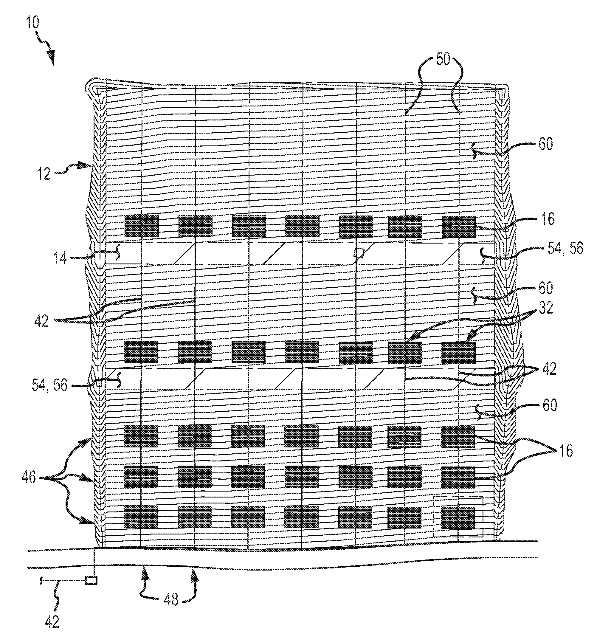
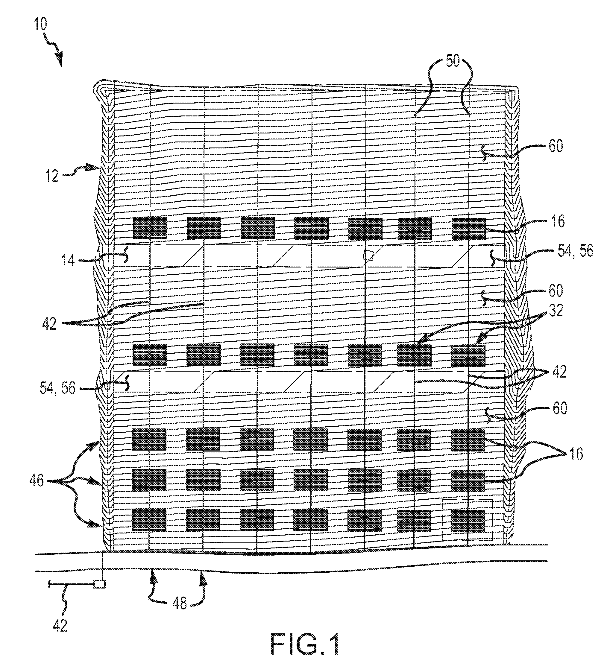
[0006]The present invention is directed to a solar landfill cover system. The solar landfill cover system does not require a 2-foot (0.610 meters) thick top vegetation / protective soil layer that is required in traditional landfill caps. The present invention eliminates the need for the top layer while still maintaining integrity of the landfill cap and while providing an alternative source of energy. The present invention further prevents UV degradation that is typically present in traditional EGC's.
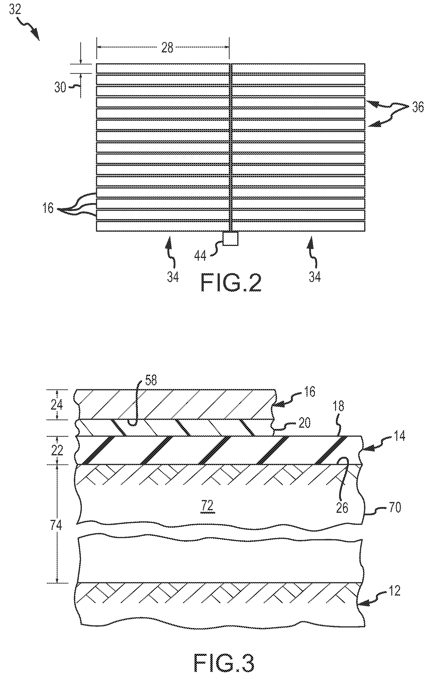
[0010]In yet another non-limiting embodiment, the invention is directed specifically to a solar landfill geomembrane. Preferably the solar landfill geomembrane comprises a flexible solar portion and a flexible water impermeable geosynthetic portion, wherein the flexible solar portion is on a top side and comprises solar cells and the geosynthetic portion is on a bottom side and comprises a layer of a flexible water impermeable geomembrane. The flexible solar portion comprises solar cells. The solar cells typically comprise of flexible thin-film photovoltaic (PV) laminates. These photovoltaic laminates are flexible, durable, and lightweight. The PV laminates are usually weatherproofed with transparent polymer coating. The power-generating layer is constructed of amorphous silicon or copper indium gallium selenide (CIGS) deposited on a thin flexible metal substrate.

Problems solved by technology

There are several problems with EGCs however.
For instance in a EGC system the geomembrane is exposed to UV rays and other weather condition which often damage and cause the geomembrane to deteriorate more quickly.
The EGC also is often not permitted by state governmental agencies due to the unpleasant aesthetic features.

Method used


Image

  • Solar Energy Cover System
  • Solar Energy Cover System
  • Solar Energy Cover System

Examples


example

[0045]One preferred non-limiting example of a solar landfill cover system and preparation of the same comprises:

[0046]Subgrade Preparation. Scarify or disc subgrade to a minimum of about 15 centimeters (about 6 inches), if necessary, to remove unacceptable large particles. Compact scarified or diced subgrade and proofroll unscarified subgrade with a steel roller having a minimum single axle weight of 10 tons. Compaction, when used, shall continue until the surface is relatively even. Subgrade material shall not have rock or gravel particles larger than about 7.6 centimeters (about 3 inches) in any dimension within the upper about 7.6 centimeters (about 3 inches) of the subgrade.

[0047]Foundation Layer. Construct foundation layer by providing soil cover to the contours and elevations indicated on the specified design drawings. The compacted soil layer forms foundation layer 70 and shall be developed by compacting successive layers having thicknesses of about 15 centimeters (about 6 in...


PUM


Abstract

A solar energy cover system, landfill cover system and method of use. The solar landfill cover system typically comprises a foundation layer of compacted soil above a solid waste pile and a solar cell geomembrane on top of the foundation layer. The solar landfill geomembrane preferably comprises a flexible solar portion and a flexible water impermeable geosynthetic portion. The flexible solar portion is on a top side and comprises solar cells and the geosynthetic portion is on a bottom side and comprises a layer of a flexible water impermeable geomembrane.

Description

CROSS-REFERENCE TO RELATED APPLICATION[0001]This patent application is based on and claims the benefit of U.S. provisional patent application Ser. No. 61 / 029,406, filed on Feb. 18, 2008, which is hereby incorporated herein by reference for all that it discloses.TECHNICAL FIELD[0002]The present invention is directed to a solar energy cover system, preferably a solar landfill cover system for covering and sealing a solid waste landfill and producing electricity from solar energy.BACKGROUND ART[0003]The safe disposal of waste is an ever growing, worldwide concern; and landfill technology has been developed to provide for the safe and economical disposal of solid waste. It is important when disposing solid waste into landfills that they be covered and sealed properly.[0004]The cap is an important part of the landfill since it serves to isolate the waste in the landfill from the exterior environment. The cap prevents the exit of pathogens, toxins and odors from the landfill and prevents ...

Claims


Application Information

Patent Timeline
IPC IPC(8): B09B5/00
CPCF24J2/36H02S20/00Y02E10/50F24S20/55H01L31/042
Inventor WALKER, TONY
Owner CARLISLE CONSTR MATERIALS
Learn More