Edge profiles for vacuum insulated glass (VIG) units, and/or VIG unit including the same

a technology of vacuum insulated glass and edge profiles, which is applied in the direction of cellulosic plastic layered products, transportation and packaging, chemistry apparatus and processes, etc., can solve the problems of adversely affecting certain low-e coatings, unsatisfactory, and long heating times of the entire assembly used in the formulation of edge seals b>4, so as to increase the likelihood of glass deformation and/or breakage, and the effect of softening the glass

Active Publication Date: 2010-11-04
GUARDIAN GLASS LLC
View PDF18 Cites 42 Cited by
  • Summary
  • Abstract
  • Description
  • Claims
  • Application Information

AI Technical Summary

Benefits of technology

[0011]Even when non-tempered glass substrates are used, the high temperatures applied to the entire VIG assembly may soften the glass or introduce stresses, and partial heating may introduce more stress. These stresses may increase the likelihood of deformation of the glass and / or breakage.
[0012]Moreover, the ceramic or solder glass edge seals of conventional VIG units tend to be brittle and prone to cracking and / or breakage, reducing the ability of individual glass panels to move relative to one another. Glass panel movement is known to occur under normal conditions such as, for example, when two hermetically sealed glass components (such as in a VIG unit) are installed as a component of a window, skylight or door, whereby the VIG unit is exposed to direct sunlight and one glass panel has higher thermal absorption than the other panel or there is a great difference between the interior and exterior temperatures.
[0013]FIG. 5 is an example conventional VIG unit. In the FIG. 5 VIG unit, first and second glass substrates 2 and 3 with flat edges are used, with the first substrate 2 being slightly smaller than the second substrate 3. The offset typically is about 3-4 mm around the glass perimeter. This design allows the glass frit 4 to be easily applied to the edges in an open environment. The bonding between the frit 4 and the first substrate 2 mainly occurs on two surfaces, namely, the lower surface 2a and the side surface 2b of the first substrate 2. There also is some bonding on the small seamed surface 2c at the corner of the first substrate 2. The slanting main body portion 4a of the glass frit 4 helps retain the frit effectively, with a portion 4b of the frit being allowed to flow into the gap 6 between the first and second substrates 2, 3 by capillary force. Unfortunately, the weight is loaded on the larger second substrate 3 when the unit is installed vertically, putting the larger second substrate 3 under a higher stress in comparison to the VIG unit designs where equally-sized substrates are used. In addition, when the frit is in a small capillary, the edge seal tends be narrow and thus weak.

Problems solved by technology

Unfortunately, the aforesaid high temperatures and long heating times of the entire assembly utilized in the formulation of edge seal 4 are undesirable, especially when it is desired to use a heat strengthened or tempered glass substrate(s) 2, 3 in the vacuum IG unit.
Moreover, such high processing temperatures may adversely affect certain low-E coating(s) that may be applied to one or both of the glass substrates in certain instances.
Such a significant loss (i.e., 80% loss) of temper strength is of course undesirable.
This may or may not be desirable in some instances.
Even when non-tempered glass substrates are used, the high temperatures applied to the entire VIG assembly may soften the glass or introduce stresses, and partial heating may introduce more stress.
These stresses may increase the likelihood of deformation of the glass and / or breakage.
Moreover, the ceramic or solder glass edge seals of conventional VIG units tend to be brittle and prone to cracking and / or breakage, reducing the ability of individual glass panels to move relative to one another.
Unfortunately, the weight is loaded on the larger second substrate 3 when the unit is installed vertically, putting the larger second substrate 3 under a higher stress in comparison to the VIG unit designs where equally-sized substrates are used.
In addition, when the frit is in a small capillary, the edge seal tends be narrow and thus weak.
In both cases, it would be difficult to retain the frit 4 unless some additional techniques are used to hold the molten frit in place, e.g., during the firing process.

Method used


Image

  • Edge profiles for vacuum insulated glass (VIG) units, and/or VIG unit including the same
  • Edge profiles for vacuum insulated glass (VIG) units, and/or VIG unit including the same
  • Edge profiles for vacuum insulated glass (VIG) units, and/or VIG unit including the same

Examples


Embodiment Construction

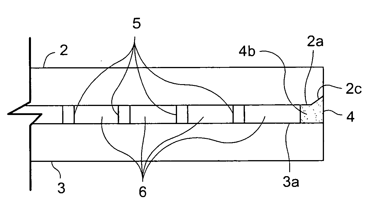
[0045]Certain embodiments of this invention relate to an improved peripheral or edge seal in a vacuum IG window unit, and / or a method of making the same. “Peripheral” and “edge” seals herein do not mean that the seals are located at the absolute periphery or edge of the unit, but instead mean that the seal is at least partially located at or near (e.g., within about two inches) an edge of at least one substrate of the unit. Likewise, “edge” as used herein is not limited to the absolute edge of a glass substrate but also may include an area at or near (e.g., within about two inches) of an absolute edge of the substrate(s). Also, it will be appreciated that as used herein the term “VIG assembly” refers to an intermediate product prior to the VIG's edges being sealed and evacuation of the recess including, for example, two parallel-spaced apart substrates. Also, while a component may be said to be “on” or “supported” by one or more of the substrates herein, this does not mean that the ...


PUM

PropertyMeasurementUnit
temperatureaaaaaaaaaa

Abstract

Certain example embodiments of this invention relate to vacuum insulated glass (VIG) units. The VIG unit may comprise first and second substrates with inner and outer substantially planar surfaces. For either or both of the first and second substrates, when considered along a side cross-section, a portion of the inner planar surface is removed proximate to an outer edge of the glass substrate so as to form a shoulder portion. An inner surface of the shoulder portion is angled (a negative number of degrees, zero degrees, or a positive number of degrees) relative to the inner and outer planar surfaces. The shoulder portion at its smallest height is at least about 50% of the glass substrate at its largest height. A side portion of the step proximate the edge also may be angled, e.g., so that it is or is not perpendicular to the planar surfaces.

Description

FIELD OF THE INVENTION[0001]Certain example embodiments relate to glass edge profiles for vacuum insulated glass (VIG) units, e.g., for VIG units having two equally-sized lites. More particularly, certain example embodiments relate to VIG units where at least one lite thereof has a step feature at an edge thereof. The edge profiles of certain example embodiments are advantageous, for example, because they provide additional surface area to which the frit may attach, thereby improving edge seal quality. In addition, in certain example embodiments, depending on the shape of the edge profile, additional advantages such as easier frit application, better frit retention, etc., may be realized. Better frit retention, in turn, may be particularly advantageous with small capillary VIG unit designs and / or in applications where the glass surface is wetted, e.g., as are sometimes used with lead-free frits.BACKGROUND AND SUMMARY OF EXAMPLE EMBODIMENTS OF THE INVENTION[0002]Vacuum IG units are k...

Claims


Application Information

Patent Timeline
Patent Type & Authority Applications(United States)
IPC IPC(8): B32B17/00C03C27/10
CPCE06B3/66304E06B3/66333E06B3/66357Y10T428/24777E06B2003/66338Y10T428/24479E06B3/677
Inventor WANG, HONG
Owner GUARDIAN GLASS LLC
Why Eureka
Try Eureka