Integrated multi-sensor component

a multi-sensor and component technology, applied in the field of sensors, can solve the problems of reducing the probability that the heating control system recognizes an incorrect, the proper functionality of the additional sensors is not known with any greater confidence, and the thermocouple degrades over time, so as to achieve the effect of adding accuracy

Inactive Publication Date: 2010-11-04
R W BECKETT
View PDF26 Cites 35 Cited by
  • Summary
  • Abstract
  • Description
  • Claims
  • Application Information

AI Technical Summary

Benefits of technology

[0019]Thus, by incorporating into one sensor housing multiple sensors, the multi-sensor component of the present invention eliminates the need for separate and relatively costly medium presence detection (e.g., low water cutoff) devices and controls (e.g., related relays, power supplies, and microprocessors) currently used in conventional HVAC systems.
[0026]Thus, by applying parameters specific to the temperature detector, pressure detector and heater of a sensor used in a monitoring system, added accuracy is obtained in determining, for example, the temperature response level for the applicable medium used in the HVAC system using the algorithms of the present invention. Further, it is anticipated that the algorithms used in the methods and temperature monitoring system of the present invention may be used to identify degradation of the sensor in order to predict a future potential sensor system failure therein.

Problems solved by technology

Two or more such sensors may reduce the probability of the heating control system recognizing an incorrect temperature, however, the proper functionality of the additional sensors are not known with any greater confidence than the initial sensor.
It is well known, however, that thermocouples degrade over time due to chemical and metallurgical changes in the composition of the materials.
Most temperature sensors used in these HVAC applications, whether used in industrial, commercial, or residential markets, eventually suffer from some form of serious degradation and / or failure of the sensor.
Such degradation or failure modes of temperature detectors include thermal degradation, metal fatigue, and corrosion, chemical and mechanical changes, which may render the sensor inoperable or induce a system failure.
Heating applications likely produce the greatest potential for sensor failures, where the sensor is particularly susceptible to extremes of thermal degradation and chemical changes.
The exposed portion of the sensor is often the hottest portion of the measurement circuit and may therefore be exposed to the harshest conditions.
These HVAC sensors are also exposed to processes that may increase the likelihood of changes in the electrical properties of the sensor or cause a complete system failure.
In boiler applications, for example, temperature, pressure, flow, and medium presence detection may be used, wherein the failure of a temperature sensor or an associated low water level cutoff detector may cause a boiler malfunction or failure.
Thus, the failure of such boiler sensors poses a problem.
In furnace applications, the temperature sensors and / or limit detectors used in a heat exchanger of a furnace may also reach very high temperatures, and cause overheating conditions that could cause the system to fail.
However, the use of these numerous individual sensors also requires more system mounting difficulties, additional wiring and added complexity in support of the remaining portion of the control system.
Such additional support components and circuitry may include related relays, power supplies, and microprocessors that increase the overall cost and complexity of the system.

Method used


Image

  • Integrated multi-sensor component
  • Integrated multi-sensor component
  • Integrated multi-sensor component

Examples


Embodiment Construction

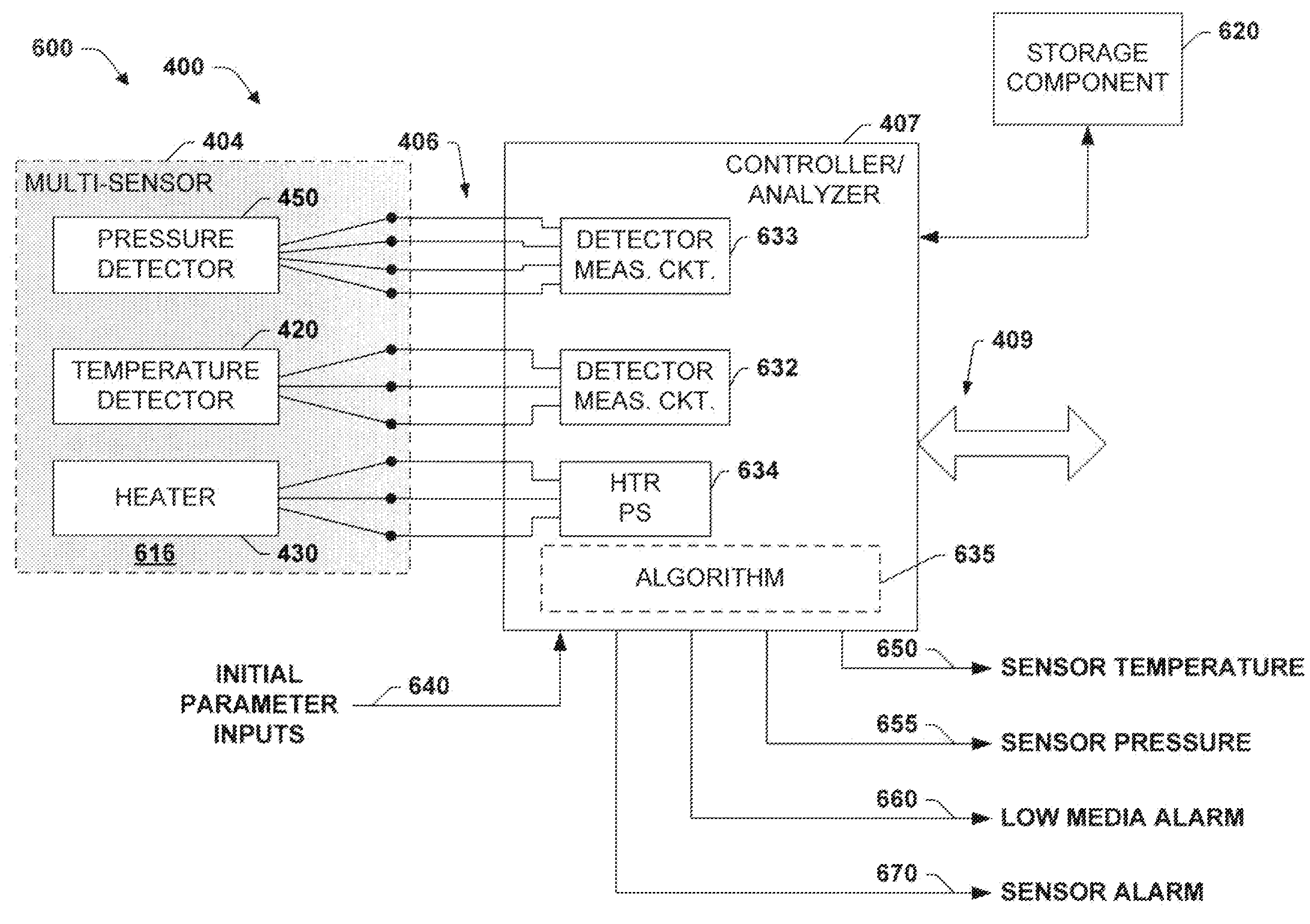
[0045]The present invention will now be described with reference to the attached drawings, wherein like reference numerals are used to refer to like elements throughout. The invention relates to a fail-safe multi-sensor component and method for detecting a temperature, pressure and the presence of an object or a medium within a heating, ventilating, and air-conditioning (HVAC) system or another such system in a fail-safe manner. The fail-safe sensor of the present invention incorporates the functions of a heater a temperature detector and pressure detector within a single sensor housing. In one aspect of the invention, the fail-safe sensor of the present invention comprises a heater such as a resistive heating element that is operable to heat the multi-sensor component to an expected temperature as measured by the temperature detector, for example, when supplied with power.

[0046]In one implementation, the temperature detector of the multi-sensor component comprises one or more of an...


PUM

PropertyMeasurementUnit
temperatureaaaaaaaaaa

Abstract

A system and method is presented for a multi-sensor component for an HVAC system. The multi-sensor component comprises a sensor assembly, having a temperature detector for measuring a temperature of an object or medium, a presence detector to detect the presence of the object or medium against the sensor, and a pressure detector for measuring a pressure of the medium. The temperature, presence and pressure detectors may also be affixed within a single sensor housing. In a heating mode the multi-sensor component is heated by a heater, and in a cooling mode the multi-sensor component cools toward a temperature of the object or medium, and the temperature detector provides temperature data indicative of a temperature response comprising one of a temperature change, a rate of change and a time constant of a thermal decay rate of the multi-sensor component and the presence of the object or medium.

Description

FIELD OF INVENTION[0001]The present invention relates generally to sensors and more particularly to sensor systems and algorithms that operate in a fail-safe manner to detect the temperature, pressure and presence of a medium within a heating, ventilating, or air-conditioning (HVAC) system.BACKGROUND OF THE INVENTION[0002]Heating systems employ various methods to control the temperature of components within the system. The temperatures of these components are usually regulated within a particular range in order to maintain safe operation. Two such components that require regulation are heat exchangers of furnaces and the water inside a pressurized hot water boiler. Redundant sensors are often used in safety-related components such as these, which provide greater confidence that the sensors are operating properly. Two or more such sensors may reduce the probability of the heating control system recognizing an incorrect temperature, however, the proper functionality of the additional ...

Claims


Application Information

Patent Timeline
Patent Type & Authority Applications(United States)
IPC IPC(8): G01K13/00G01K3/00G06F15/00
CPCF24F11/001F24F2011/0052G01K2201/00G01K7/42G01K3/10F24F11/30F24F2110/00F24F11/32F24F11/88
Inventor BOHAN, JOHNBUTKOWSKI, JOHNBEIGHT, TIMOTHYFIIDES, CHRISTOPHER
Owner R W BECKETT
Why Eureka
Try Eureka