
Underwater Gun Comprising a Plate-Type Barrel Seal

Inactive Publication Date: 2010-11-11
LOCKHEED MARTIN CORP
View PDF8 Cites 5 Cited by
  • Summary
  • Abstract
  • Description
  • Claims
  • Application Information

AI Technical Summary

Benefits of technology

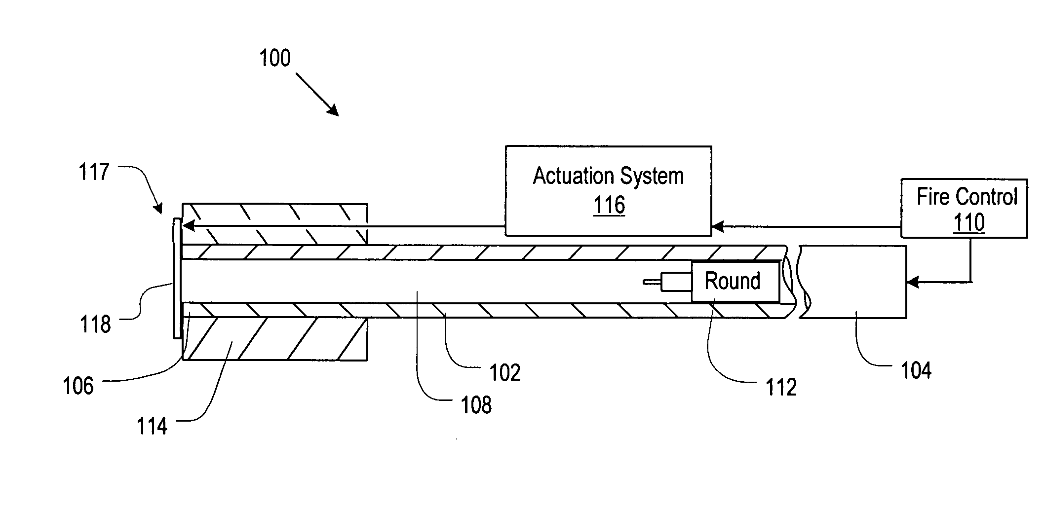
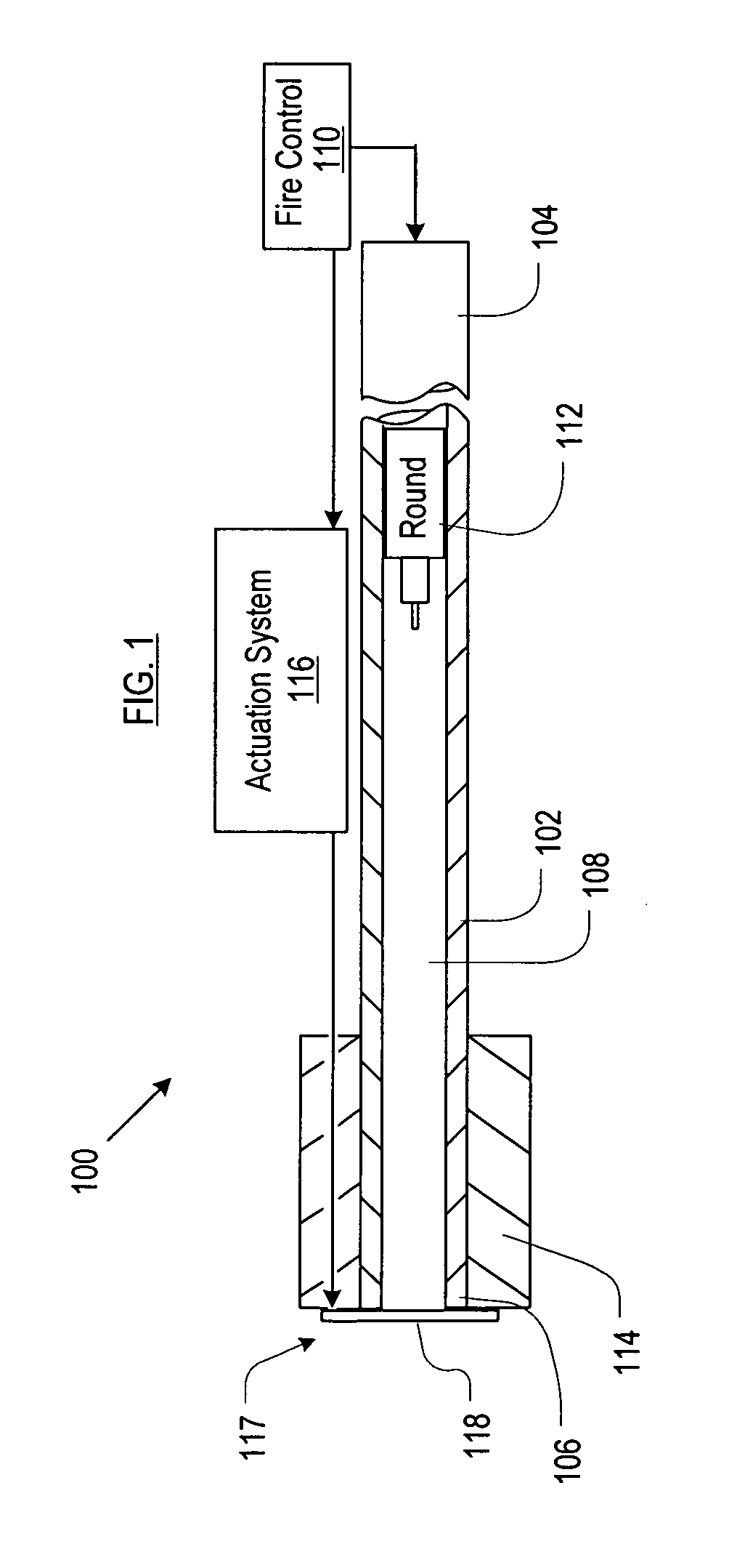
[0009]The present invention provides an underwater gun having a plate-type barrel seal for preventing water from entering the barrel between the firing of rounds.
[0010]In the illustrative embodiment, the barrel seal comprises one or more disks that, by virtue of an actuation system, are moved between a “sealing” state and a “firing” state. In the sealing state, the disk is axially aligned with and abuts the muzzle end of the gun's barrel, thereby substantially preventing water from entering the barrel. In the firing state, the disk is moved out of axial alignment with the barrel such that a round is free to exit the barrel without interference from the disk.

Problems solved by technology

A gun, especially one with a high muzzle velocity, cannot be fired when water is in its barrel.
If a firing where to incur in a water-filled barrel, a very high breach pressure would result as the ignited propellant charge forces (or tries to force) the water out of the barrel.
The likely result would be material failure of the barrel.
Notwithstanding the many approaches to the problem, no truly satisfactory approach has been developed for keeping water out of the barrel of an underwater gun between and during operation.

Method used


Image

  • Underwater Gun Comprising a Plate-Type Barrel Seal
  • Underwater Gun Comprising a Plate-Type Barrel Seal
  • Underwater Gun Comprising a Plate-Type Barrel Seal

Examples


first embodiment

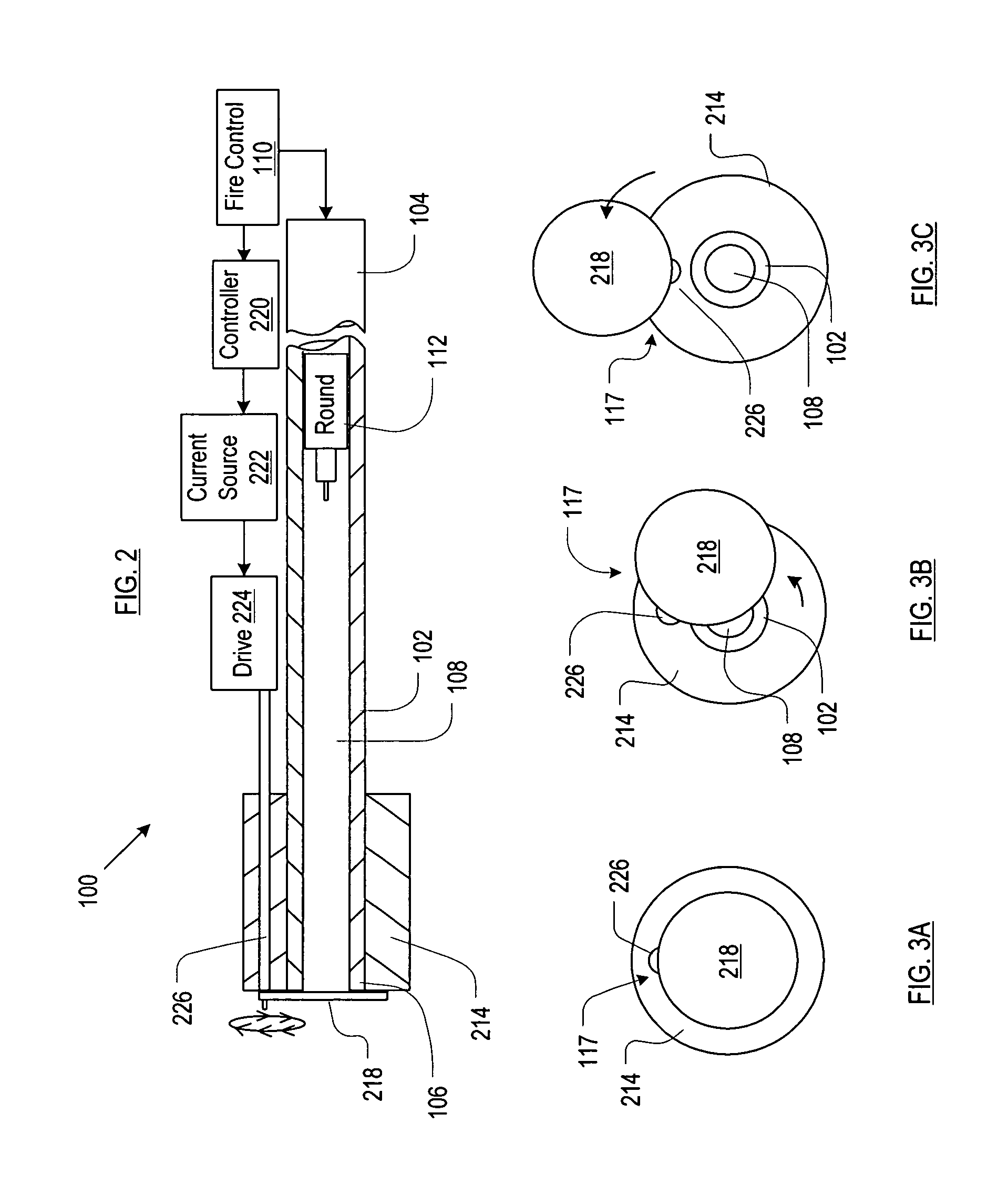
[0040]FIG. 2 depicts a plate-type barrel seal for use in conjunction with underwater gun 100. FIG. 2 depicts barrel 102 of gun 100 in a sealed state.

[0041]In the embodiment that is depicted in FIG. 2, actuation system 116 comprises controller 220, current source 222, drive 224, and drive shaft 226, interrelated as shown.

[0042]Controller 220 includes a microprocessor that is capable of receiving a signal from fire-control system 110 and taking action responsive thereto. In some embodiments, that action is to generate a signal that causes current source 222 to deliver current or stop delivering current. Drive 224, when energized with current from current source 222, is operable to turn driveshaft 226. In some embodiments, drive 224 is an electric motor.

[0043]Plate arrangement 117 is operatively coupled to drive shaft 226. The movement of the drive shaft is controlled, ultimately, by fire-control system 110. More particularly, fire-control system 110 directs controller 220 to cause cur...

second embodiment

[0046]FIGS. 4A and 4B depict plate arrangement 117 for use in conjunction with the plate-type barrel seal. In particular, the plate arrangement comprises two disks 218A and 218B that are operatively coupled to drive shaft 226. The barrel seal moves from a firing (or sealing) state to the opposite state by rotating drive shaft 226 by ninety degrees. For example, FIG. 4A depicts plate arrangement 117 in a firing state, wherein neither disk 218A nor disk 218B occludes barrel 102. As drive shaft 226 moves ninety degrees counter clockwise, disk 218A is moved into axial alignment with barrel 102, thereby placing the barrel seal in the sealing state. In some embodiments, a stepper motor is used as drive 224. Alternatively, any of a variety of mechanical linkage arrangements suitable for creating a stepped movement, as known to those skilled in the art, can be used in conjunction with a motor.

[0047]It will be appreciated that fire-control system 110 must synchronize the operation of the bar...


PUM


Abstract

An apparatus for sealing the barrel of an underwater gun between firings is disclosed. The apparatus comprises a magnetically-attractable water-impermeable disk. Via operation of a drive system, the disk is movable between a sealing position, wherein it prevents water from entering the barrel by moving into alignment with the first bore, and a firing position, wherein the first water-impermeable disk moves out of alignment with the first bore.

Description

CROSS REFERENCE TO RELATED APPLICATIONS[0001]This case is related to the following U.S. patent applications: Atty. Dkt. Nos.: 711-196us (Underwater Gun Comprising a Valve-Type Barrel-Seal), 711-197us (Underwater Gun Comprising a Barrel Adapter including a Barrel Seal), 711-199us (Underwater Gun Comprising a Passive Fluidic Barrel Seal), and 711-200us (Underwater Gun Comprising a Turbine-Based Barrel Seal), all of which were filed on even date herewith and all of which are incorporated by reference herein.FIELD OF THE INVENTION[0002]The present invention relates to underwater guns.BACKGROUND OF THE INVENTION[0003]Underwater guns are useful as anti-mine and anti-torpedo devices. Recently, autonomous underwater vehicles (AUVs) have been fitted with underwater guns for torpedo defense and underwater “hunter-killer” CONOPs.[0004]A gun, especially one with a high muzzle velocity, cannot be fired when water is in its barrel. If a firing where to incur in a water-filled barrel, a very high ...

Claims


Application Information

Patent Timeline
IPC IPC(8): F41C9/06
CPCF41A21/32F41F3/08F41C9/06F41F3/10
Inventor FU, JYUN-HORNGHOWARD, ROBERT JAMESRAPP, JOHN W.PAULIC, ANTONIO
Owner LOCKHEED MARTIN CORP
Learn More