Double-Clamp Earth Tester Device

a tester device and double-clamp technology, applied in measurement devices, voltage/current isolation, instruments, etc., can solve the problems of large size and weight of the whole device, method can pose a safety risk to the equipment being protected and to the users of that equipment, and the method can be very time-consuming, so as to improve the accuracy of the device

Inactive Publication Date: 2010-11-11
MEGGER
View PDF6 Cites 26 Cited by
  • Summary
  • Abstract
  • Description
  • Claims
  • Application Information

AI Technical Summary

Benefits of technology

[0051]The compensation techniques of the invention have particular benefit by enabling the transformer cores to be located closer together than would otherwise be possible, ye

Problems solved by technology

Such methods can be very time consuming, because they require manual insertion of the auxiliary metal electrodes 14; 22 into the soil 16 at least tens of meters away A, B from the electrode under test 12, with an attendant need for long leads 18; 24 to connect those metal electrodes with the electrode under test 12.
Furthermore, such methods can pose a safety risk to the equipment being protected and to the users of that equipment if the electrode under test 12 is to be disconnected at any time and there are substantial leakage currents present.
However, this meant a non-optimum approach leading to large size and weight of the whole device.
This is known to adversely affect the measurement accuracy, due to unwanted signals parasitically induced in the CT 32 as a direct result of the electromagnetic field 40 emanating from the VT 30, in addition to the useful signals induced as a result of the voltage deliberately induced in the loop under test.
The amplitude and phase of the field 40 changes with the gap 41a in a highly non-linear manner and even a small gap of a few micrometers can adversely affect the measurement to unacceptable level, due to the highly non-linear nature of the interference.
However, access to the electrode 12 to be tested is often very limited, so the user might be forced to operate the clamps 30′, 32′ much closer to each other than the optimal, interference-free distance.
This inevitably leads to unreliable measurement results.
This significantly increases the cost of the device and still

Method used


Image

  • Double-Clamp Earth Tester Device
  • Double-Clamp Earth Tester Device
  • Double-Clamp Earth Tester Device

Examples


Embodiment Construction

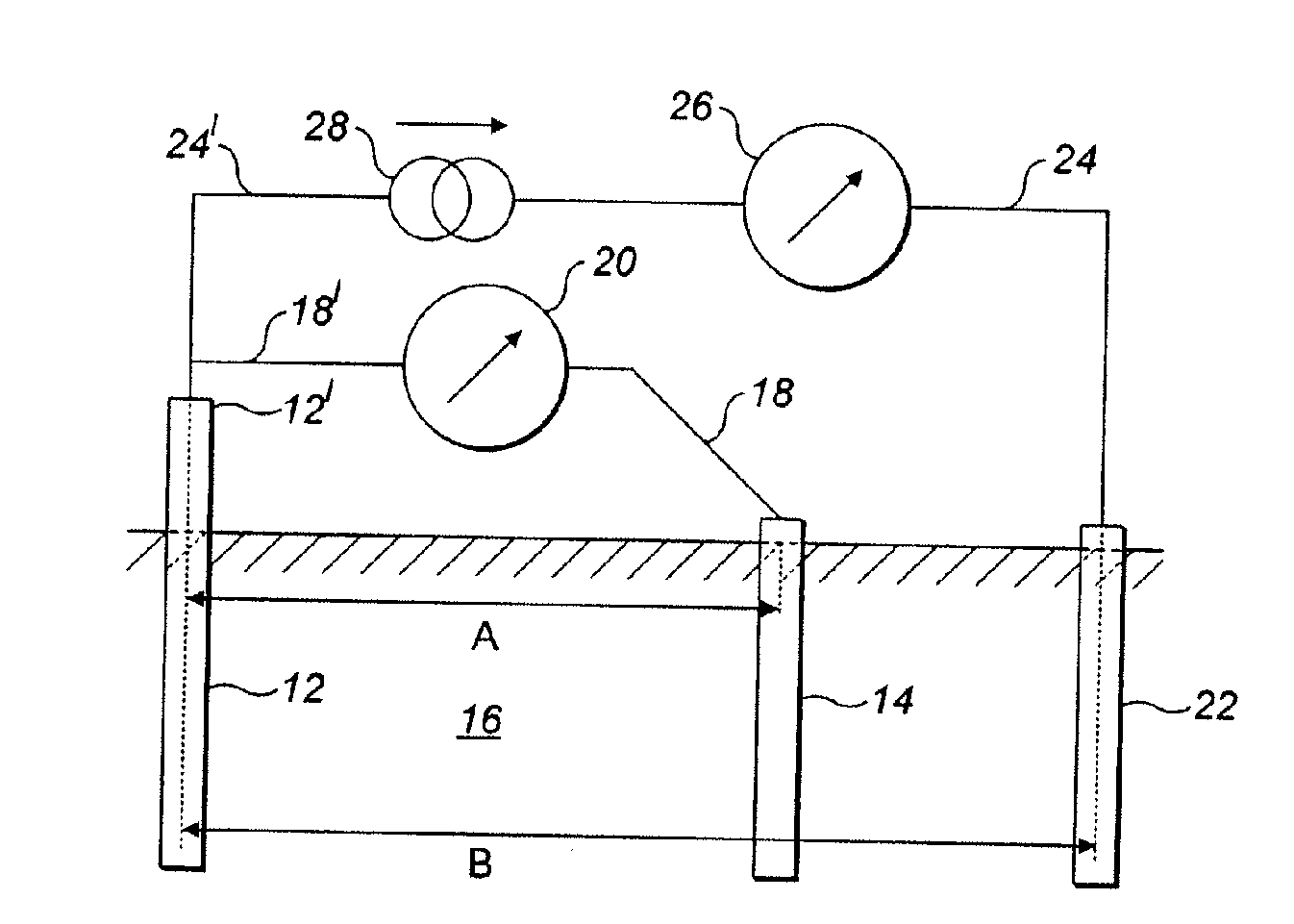
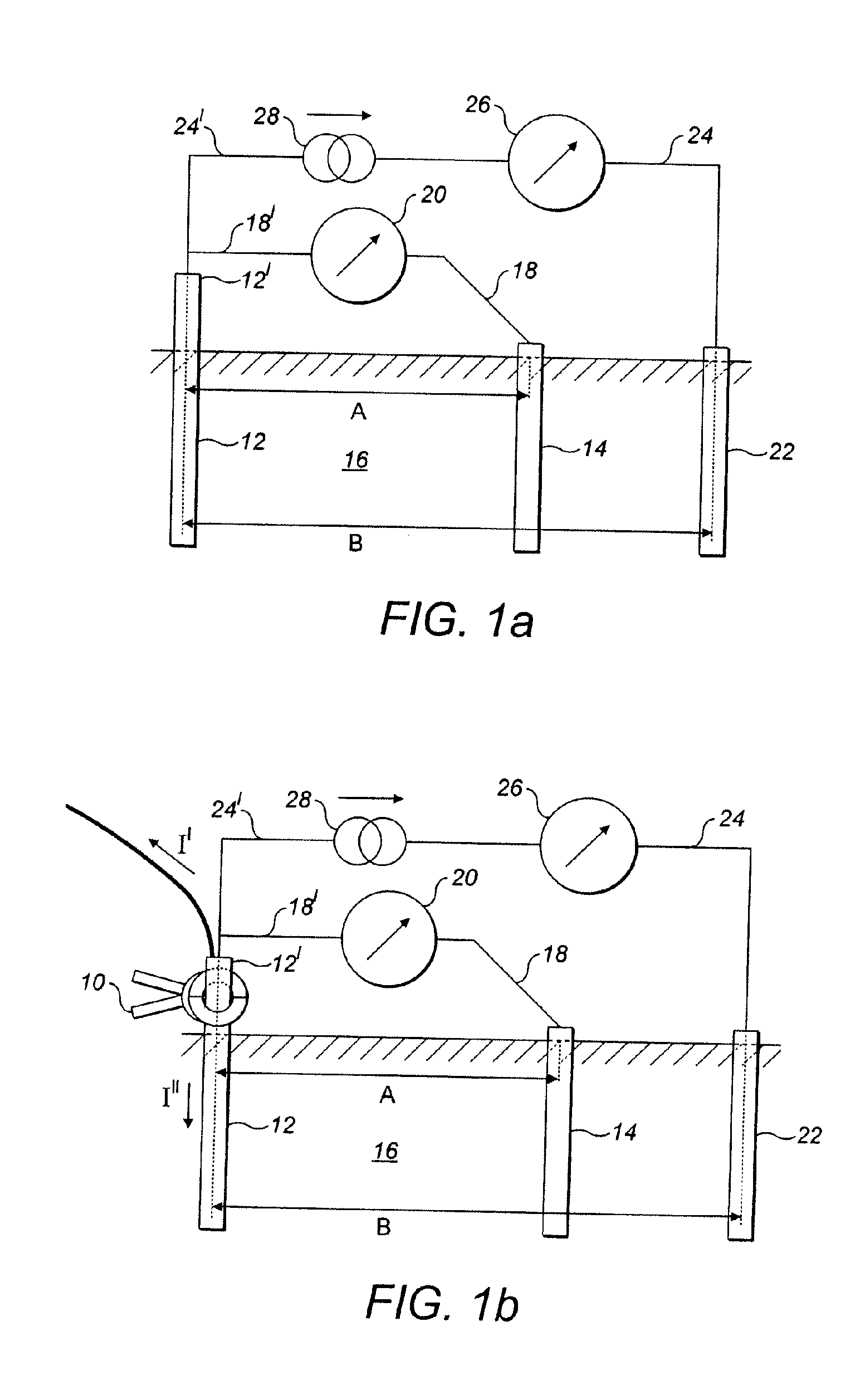
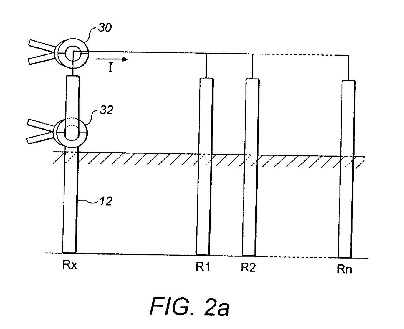
[0069]A typical double-clamp device is shown schematically in FIG. 7. The double-clamp device consists typically of a voltage-inducing transformer (VT) 30 with one or more turns of a primary winding 31 and a current-sensing transformer (CT) 32 which has a secondary winding 33 with one or more turns.

[0070]In use, both transformers 30, 32 clamp around an electrode under test, which is represented by the loop 60 of equivalent resistance having certain impedance Zloop 62, as discussed above by reference to FIG. 2. The voltage-inducing transformer core 44 and the current-sensing transformer core 46 are typically integrated into a head portion of the device.

[0071]A signal processing unit 35 supplies voltage to the VT 30. The voltage supplied through the primary winding 31 induces an electromagnetic field in the VT core 44, which in turn induces a current to flow in the loop 60. That current flowing in the loop 60 induces a desired magnetic field Hloop 64 in the CT core 46. However, an unw...


PUM


Abstract

A double-clamp earth tester device, having a voltage-inducing transformer (VT) (30), a current-sensing transformer (CT) (32), a voltage source adapted to supply a voltage across a primary winding (31) on the VT core (44) and a signal processing unit (35) adapted to measure a resultant signal output from a secondary winding (33) on the CT core (46), is susceptible to errors induced by electromagnetic interference between the cores (44, 46) of the two transformers. Previously, the effects of this interference have been mitigated by surrounding one or both cores (44, 46) with electromagnetic shielding (42). This had lead to devices having a bulky head portion and attendant difficulties in accessing sites having restricted access (52). These problems have been overcome by providing means to modify the signal output form the secondary winding (33). This may be achieved magnetically by nullifying the parasitic magnetic fields (66) at source in the core (46) of the current-sensing transformer, or electrically by the addition of a negative signal to the output signal prior to or during processing in the signal processing unit (35).

Description

[0001]This application claims priority from European Patent Application 09159431.7, filed May 5, 2009, which is incorporated herein by reference.FIELD OF THE INVENTION[0002]Electrical installations must be grounded or earthed because this is essential for the safety of equipment, users and operating personnel. The earthing is achieved by connecting a suitable conductor, the protective earth, to a soil-buried conductive element such as a rod, bar, pipe or pylon. The resistance of this earthing electrode must be sufficiently low in order to provide requisite electrical protection, i.e. to dissipate an expected fault current thereby to reduce the likelihood of dangerous voltages arising. National and international standards define such required levels of protection.[0003]The condition of the earthing electrodes and the value of the resistance of earthing electrodes (in short referred to as “earth resistance”) should be inspected periodically, and there are a number of ways in which thi...

Claims


Application Information

Patent Timeline
IPC IPC(8): G01R27/08G01R15/18
CPCG01R31/026G01R27/20G01R31/52G01R31/54
Inventor ZUREK, STANISLAWMYNOTT, STEPHENHAMMETT, DANIEL SCOTTGOSFORD, OWEN THURSTAN
Owner MEGGER
Why Eureka
Try Eureka