Harmonic rejection mixer unit and method for performing a harmonic rejection mixing

a mixer unit and harmonic rejection technology, applied in the direction of instruments, electric/magnetic computing, computation using denominational number representation, etc., can solve the problems of affecting the linearity and affecting the performance of the mixer

Active Publication Date: 2010-11-11
NXP BV
View PDF5 Cites 14 Cited by
  • Summary
  • Abstract
  • Description
  • Claims
  • Application Information

AI Technical Summary

Benefits of technology

[0024]Further aspects are def

Problems solved by technology

Therefore, several unwanted conversion or multiplication components may be present at the output of the mixer.
However, in general, a bad noise and a bad linearity performance is present.
However, harmonic rejection mixers according to the prior art suffer from a bad noise performance as compared to basic switching mixers.
Mo

Method used


Image

  • Harmonic rejection mixer unit and method for performing a harmonic rejection mixing
  • Harmonic rejection mixer unit and method for performing a harmonic rejection mixing
  • Harmonic rejection mixer unit and method for performing a harmonic rejection mixing

Examples


first embodiment

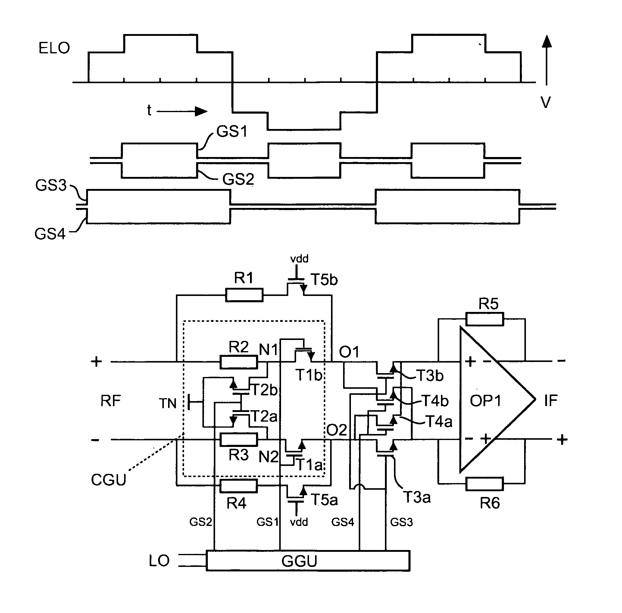
[0039]FIG. 4 shows a basic circuit diagram of a harmonic rejection mixer unit according to a In the upper part of FIG. 4, a diagram of gate signals GS1-GS4 and a resulting effective multiplication or local oscillator signal ELO of the harmonic rejection mixer is shown. The gate signals GS1-GS4 are derived from the local oscillator signal LO. The time period of the gate signal GS1 corresponds to the time period of the gate signal GS2 and is ½ of the time period of the LO or multiplication signal. However, the gate signal GS2 is inverted with respect to the gate signal GS1. The time period of the gate signal GS3 corresponds to the time period of the gate signal GS4 as well as to the time period of the LO signal. However, the gate signal GS4 is inverted with respect to the gate signal GS3.

[0040]The effective LO or multiplication signal described according to the present invention can be measured at the IF output, if a DC voltage is applied to a RF input. The effective LO or multiplica...

second embodiment

[0051]FIG. 5 shows a schematic representation of a harmonic rejection mixer according to a In the upper part of FIG. 5, a diagram of the effective local oscillator LO or the multiplication signal ELO and the gate signals GS2-GS4 are depicted. The gate signals GS2-GS4 are derived from LO signal in the gate signal generating unit GGU and can be applied to different transistor units of the harmonic rejection mixer unit. The time period of the gate signal GS2 corresponds to ½ of time period of the LO signal. The time period of the gate signal GS3 corresponds to the time period of the gate signal GS4 as well as to the time period of the LO signal. However, the gate signal GS4 is time-shifted with respect to the gate signal GS3. Compared to the original 50% duty cycle of the LO signal the duty cycle of the gate signals are reduced.

[0052]In the lower part of FIG. 5, a circuit diagram of the harmonic rejection mixer according to the second embodiment is depicted. The harmonic rejection mix...

sixth embodiment

[0069]FIG. 9 shows a block diagram of a harmonic rejection mixer according to a While in FIG. 5 a circuit diagram of the harmonic rejection mixer is depicted, FIG. 9 shows a block diagram of the harmonic rejection mixer. The harmonic rejection mixer comprises an input TN, a plurality of voltage-to-current units with different gain V21G1-V21GN, coupled to the input IN and in series with a plurality of harmonic rejection units HRU1-HRUN (wherein each V21 unit is associated with a harmonic rejection unit HRU) and a current to voltage unit 12V. The outputs of the harmonic rejection units HRU1-HRUN are summed or combined and the result thereof is input to the current-to-voltage unit 12V. The output of the current to voltage unit 12V constitutes the output of the harmonic rejection mixer. The harmonic rejection mixer furthermore comprises a transistor control signal generating unit GGU for generating transistor control signals for controlling transistors in the harmonic rejection units H...


PUM


Abstract

A harmonic rejection mixer unit is provided which comprises an input (RF), at least one harmonic rejection unit (HRU) with at least two transistor units (T3a, T3b; T4a, T4b) for multiplying an input signal from the input (RF) with a multiplication signal (ELO). The harmonic rejection mixer unit furthermore comprises a transistor control signal generating unit (GGU) for generating transistor control signals (GS1-GS4) for the at least two transistor units (T3a, T3b; T4a, T4b) of the at least one harmonic rejection unit (HRU) by deriving the transistor control signals (GS1-GS4) from a local oscillator signal (LO). The transistor control signals (GS3, GS4) for the at least two transistor units (T3a, T3b; T4a, T4b) are generated with a duty cycle of <50% and are generated such that the shape of the multiplication signal ELO) is achieved by a constructive summation of the output signals from the transistor units (T3a, T3b; T4a, T4b). The transistor control signals (GS1-GS4) are generated such that only a summation of output signals from the transistor units with the same sign or with zero is performed.

Description

FIELD OF THE INVENTION[0001]The present invention relates to a harmonic rejection mixer unit and method of performing a harmonic rejection mixing.BACKGROUND OF THE INVENTION[0002]Typical conversion circuits or mixers multiply an input signal with a local oscillator LO signal. The multiplication can for example be performed by switching the currents to obtain a low noise and high linearity result.[0003]Typical mixers like switching MOS mixer and a Gilbert cell mixer are depicted in FIG. 1. The switching MOS mixer comprises four MOS transistors TA, TB, TC, and TD. The transistors TA and TB are coupled to a first resistor Rs and the transistors TC and TD are coupled to a second resistors Rs. The two resistors Rs are coupled to an RF input of the mixer. Furthermore, an operational amplifier OP is coupled between the transistors TA, TB, TC and TD and an IF output. The transistors TA and the transistor TC are coupled to a first input of the operational amplifier OP while the transistors T...

Claims


Application Information

Patent Timeline
IPC IPC(8): G06G7/14G06G7/12
CPCH03D7/1441H03D7/166H03D7/18H03D2200/0086H03D7/165H03D7/1458H03D7/1466H03D7/1483H03D7/145
Inventor VAN SINDEREN, JANAMIOT, SEBASTIENHESSEN, LEONARDUS H. M.
Owner NXP BV
Why Eureka
Try Eureka