Miniaturized GPS/MEMS IMU integrated board

Active Publication Date: 2010-11-11
AMERICAN GNC
View PDF6 Cites 49 Cited by
  • Summary
  • Abstract
  • Description
  • Claims
  • Application Information

AI Technical Summary

Benefits of technology

[0015]Another objective of the present invention is to provide an intelligent automated system to realize autonomous navigation with capabilities to perform highly precise relative attitude and position determination, intelligent robust failure detection and isolation, advanced collision avoidance, and on-board situational awareness for contingency operations.
[0019]Because the fiducial features can be consistently detected in the images, the same features can be found in both images correctly by processing electro-optic sensor images and matching features on both images. The disparities (i.e., range) to the fiducial features can be easily computed.
[0020]A corner is another kind of feature, which exists in most kinds of objects. Corner detection utilizes the convolution between the original image and a corner mask, so it can be implemented in real time easily. The same corners can be found in both images, correctly, by processing the electro-optic sensor images and matching corners in both images. The disparities (i.e., range) to the corners can then be easily computed.
[0021]The present invention can substantially solve the problems encountered in machine vision system integration by using state-of-the-art inertial sensor, global positioning system technology, laser ranger unit enhanced with fiducial feature matching and corner matching technologies. The present invention is to make machine vision a practical application by enhancing real time and reliability.

Problems solved by technology

There are two difficult problems for machine vision systems.

Method used


Image

  • Miniaturized GPS/MEMS IMU integrated board
  • Miniaturized GPS/MEMS IMU integrated board
  • Miniaturized GPS/MEMS IMU integrated board

Examples


Embodiment Construction

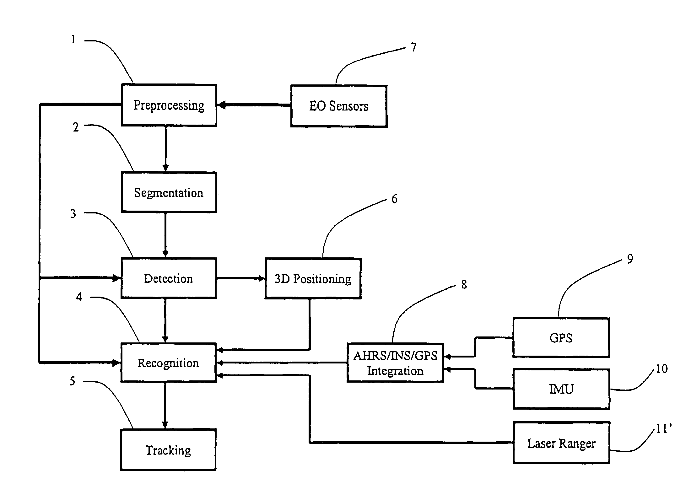
[0054]Generally, IMU / GPS integration can output the position, attitude and azimuth of the vehicle itself. A laser ranger measures the distance between the object and vehicle. Electro-optic image sensors derive the 3D environment in the field of view. The traditional electro-optic sensor image processing is time consuming and unreliable.

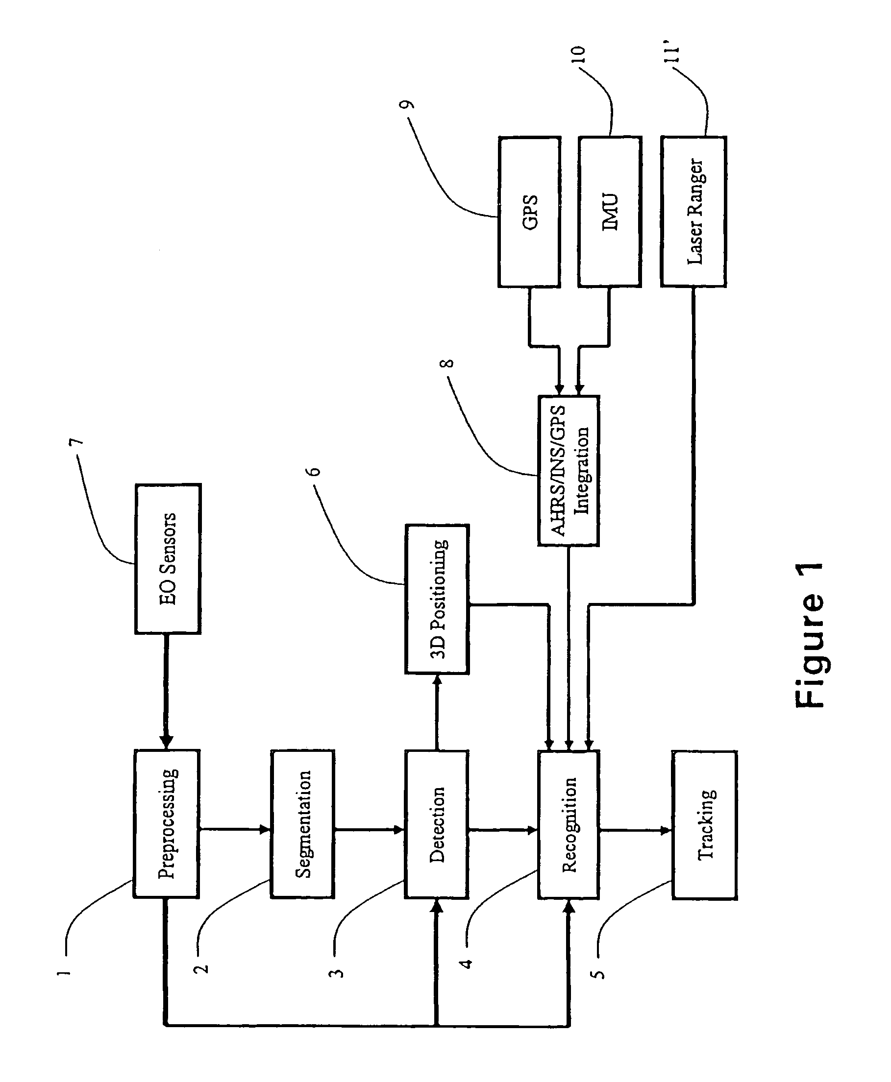
[0055]Referring to FIG. 1, the electro-optic sensor image processing comprises a preprocessing module 1, a segmentation module 2, a detection module 3, a recognition module 4, a 3D-positioning module 5, a tracking module 6, EO sensors 7, an AHRS / INS / GPS Integration module 8, a GPS receiver 9, a MEMS IMU 10, and a laser ranger 11.

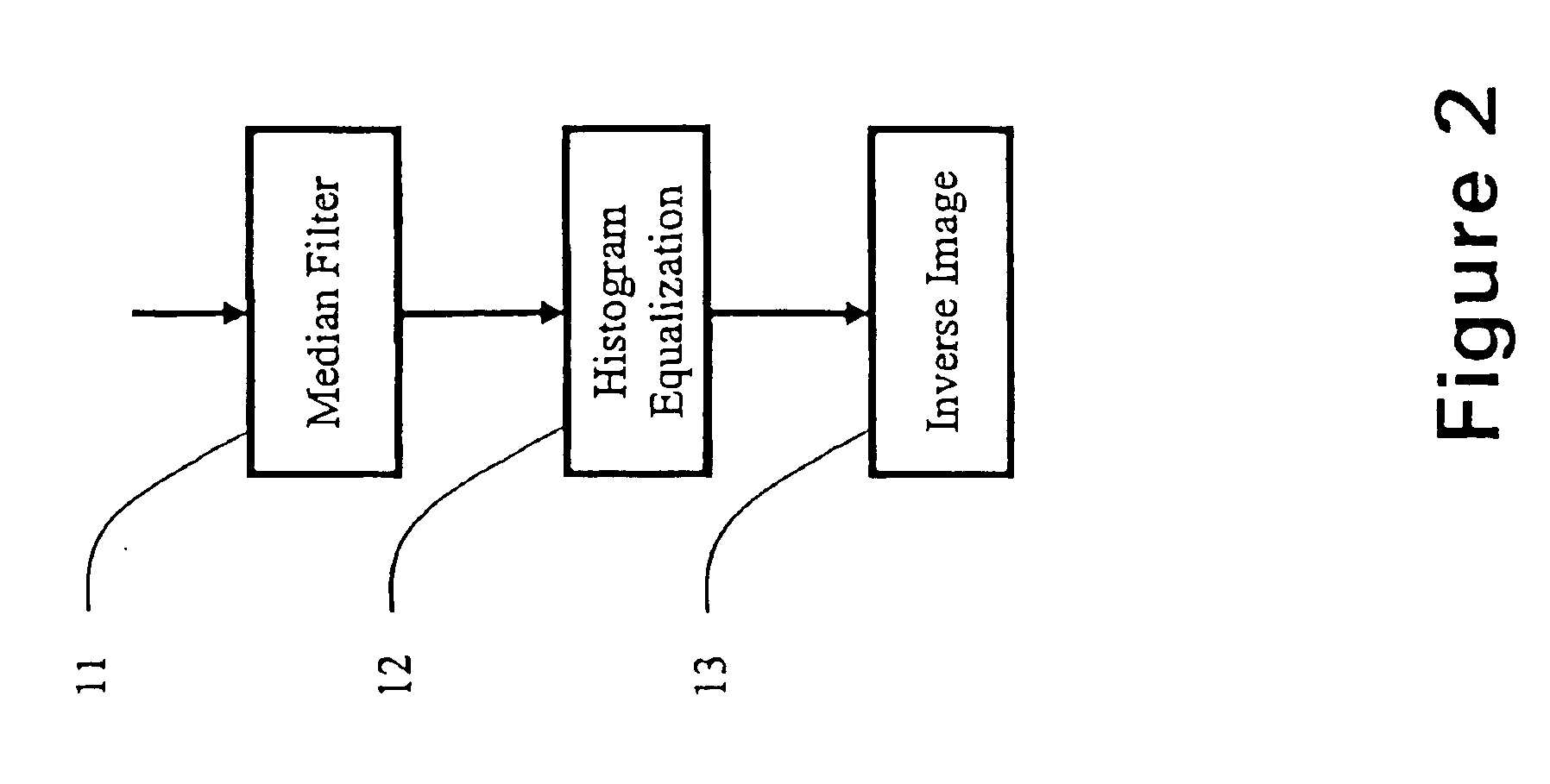
[0056]Referring to FIG. 2, the preprocessing module 1 comprises a Median Filter module 11, a Histogram Equalization module 12 and an Inverse Image module 13.

[0057]Referring to FIG. 3, the segmentation module 2 comprises a Threshold Black / White module 21, a Suppress Black module 22, a Suppress White module 23, and a Sobel Filte...


PUM


Abstract

This invention documents the efforts on the research and development of a miniaturized GPS / MEMS IMU integrated navigation system. A miniaturized GPS / MEMS IMU integrated navigation system is presented; Laser Dynamic Range Imager (LDRI) based alignment algorithm for space applications is discussed. Two navigation cameras are also included to measure the range and range rate which can be integrated into the GPS / MEMS IMU system to enhance the navigation solution.

Description

CROSS REFERENCE OF RELATED APPLICATION [0001]This is a non-provisional application of a provisional application having application No. 60 / 880345 and filing date of Jan. 12, 2007, and is a Continuation-In-Part application of application Ser. No. 10 / 912,401 filed on Aug. 4, 2004.[0002]This invention was made with Government support under contract NAS9-99024 awarded by NASA. The Government has certain rights in the invention.BACKGROUND OF THE PRESENT INVENTION [0003]1. Field of Invention[0004]The present invention relates generally to machine vision systems, and more particularly to object positioning, which employs electro-optic (EO) image sensors enhanced with integrated laser ranger, global positioning system / inertial measurement unit, and integrates this data to get reliable and real time object position.[0005]2. Description of Related Arts[0006]There are two difficult problems for machine vision systems. One is image processing speed, another is the reliability, which affect the a...

Claims


Application Information

Patent Timeline
IPC IPC(8): H04N13/02
CPCG06K9/3216G06K9/6293G06T2207/20164G06T7/0085G06T7/0044G06T7/74G06T7/13G06V10/245G06V10/811G06F18/256
Inventor LIN, CHING-FANG
Owner AMERICAN GNC
Why Eureka
Try Eureka