Image processing apparatus, image division program and image synthesising method

a technology of image processing and image synthesis, applied in the field of image processing techniques, can solve the problems of loss of polarization characteristics of incident light, and achieve the effect of accurately separating a specular reflection area

Active Publication Date: 2010-11-11
PANASONIC CORP
View PDF17 Cites 44 Cited by
  • Summary
  • Abstract
  • Description
  • Claims
  • Application Information

AI Technical Summary

Benefits of technology

[0053]With an image process of the present invention, it is possible to accurately separate a specular reflection area and a diffuse reflection area from each other by using two kinds of information, i.e., the light source condition dependency and the polarization information. More

Problems solved by technology

Since the diffuse reflection occurs through repeated scattering, the polarization characteristics of the incident light have been

Method used


Image

  • Image processing apparatus, image division program and image synthesising method
  • Image processing apparatus, image division program and image synthesising method
  • Image processing apparatus, image division program and image synthesising method

Examples


first embodiment

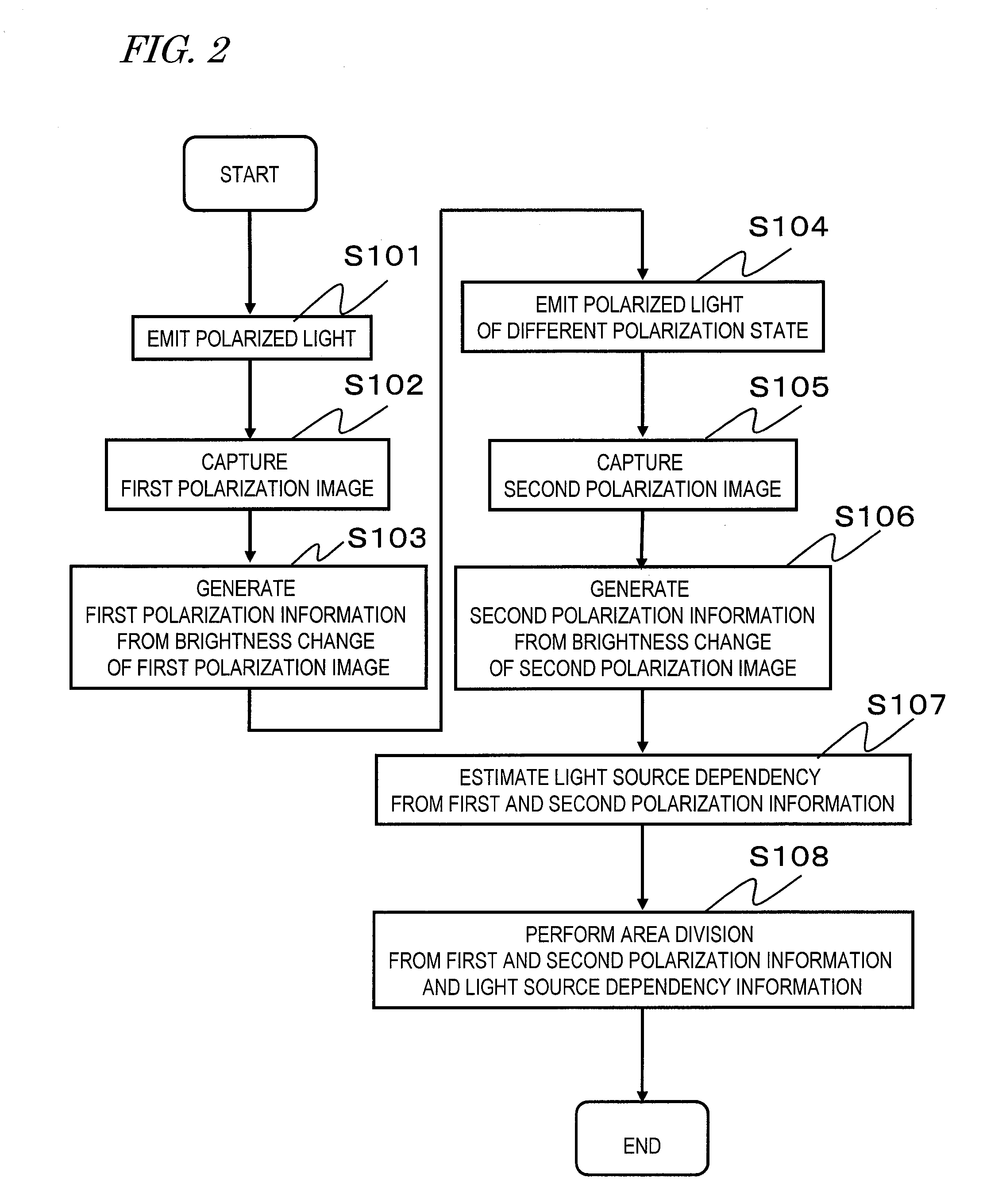
[0131]First, the outline of an image processing apparatus according to a first embodiment of the present invention will be described. The image processing apparatus of the present embodiment calculates the light source dependency by changing the polarization state of the illumination section (light source). An area division of the object is performed by using the polarization information and the light source dependency resulting from the change of the polarization state.

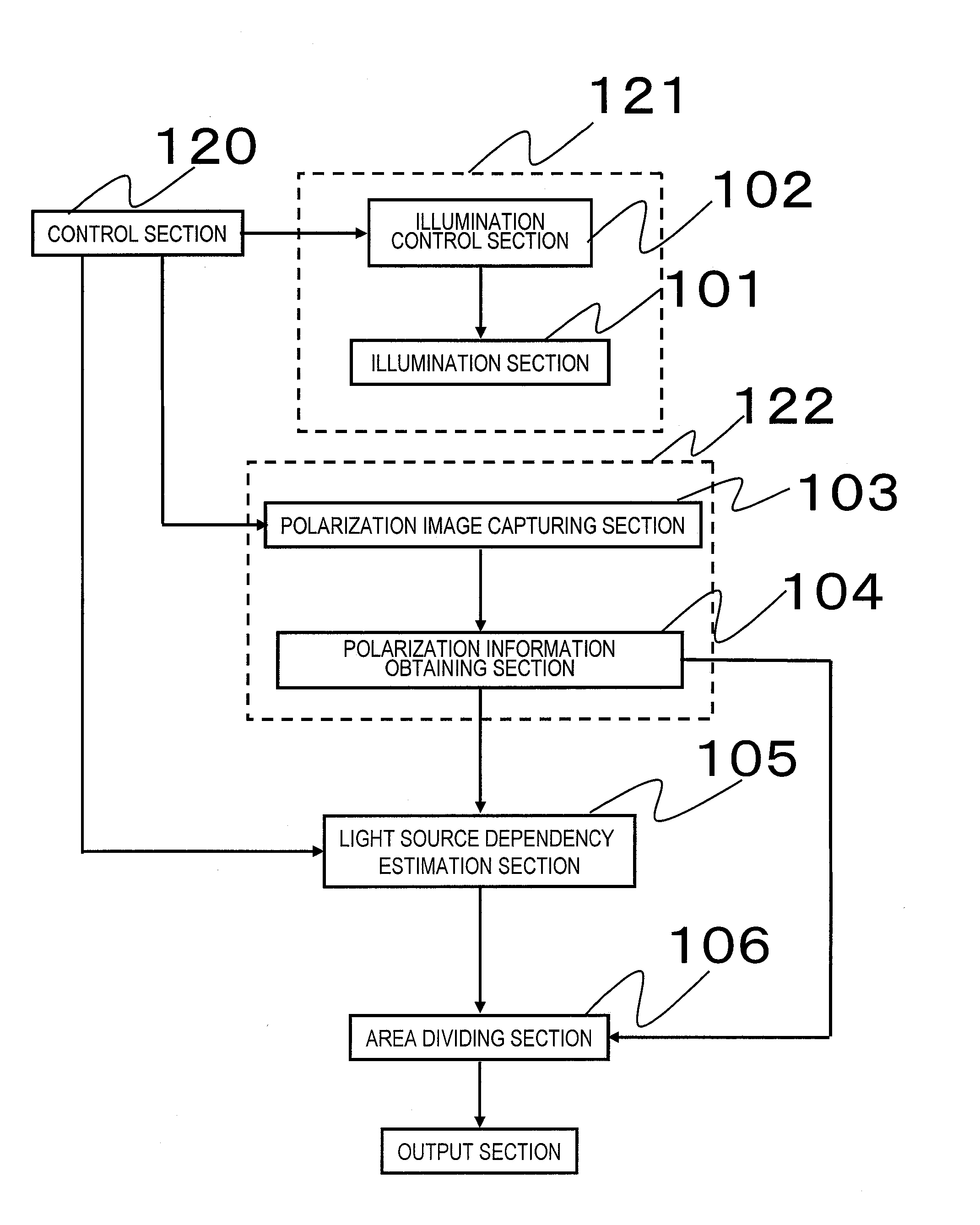
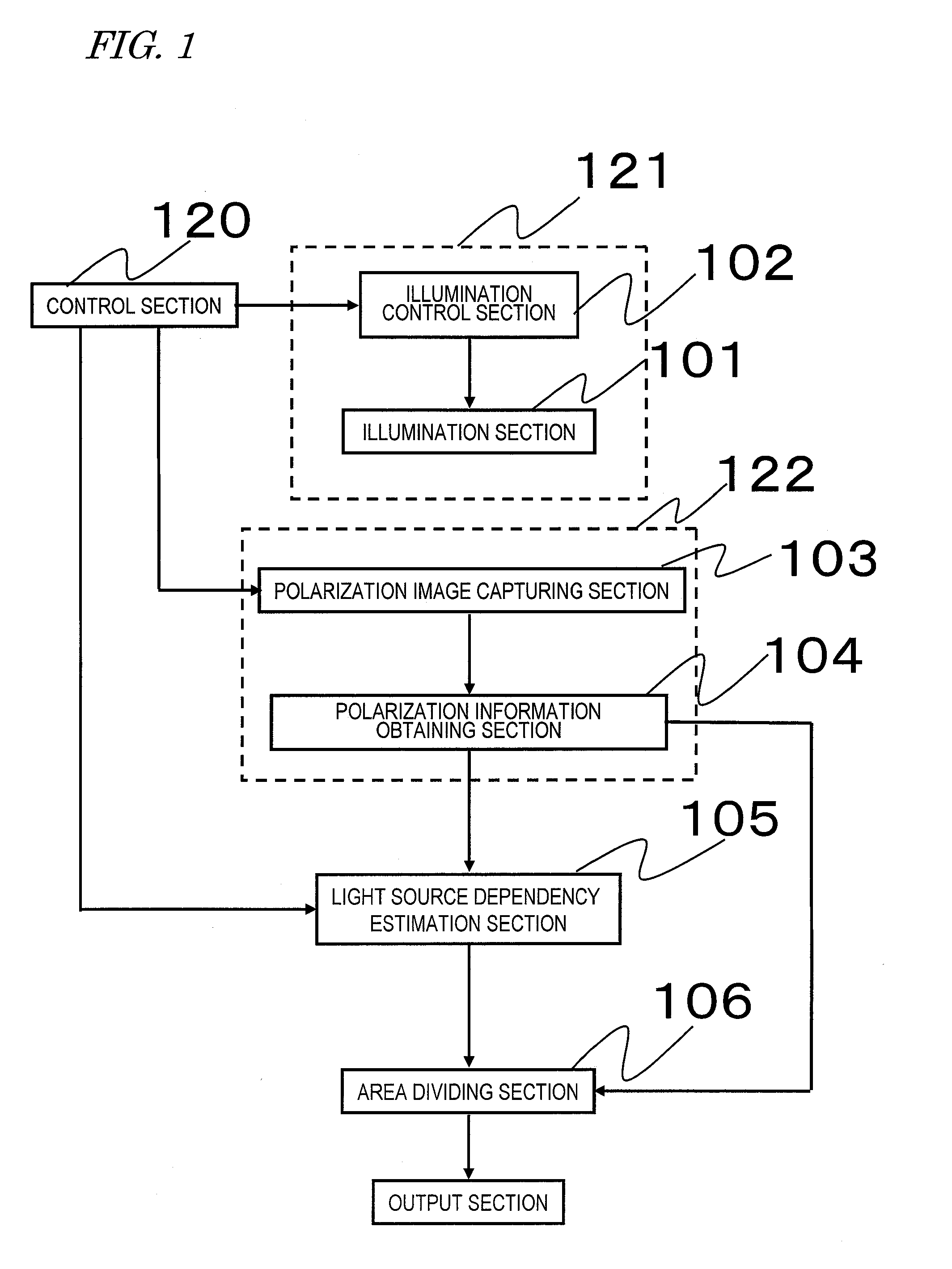
[0132]FIG. 1 is a block diagram showing the image processing apparatus of the present embodiment. The image processing apparatus is an apparatus for capturing an image of the object and thereby dividing (performing an area division of) the surface of the object into a plurality of areas of different optical properties.

[0133]The image processing apparatus includes: an illumination unit 121 for emitting linearly-polarized light onto the object while changing the polarization state thereof; a polarization information ob...

second embodiment

[0217]Next, the outline of an image processing apparatus according to a second embodiment of the present invention will be described. The image processing apparatus of the present embodiment calculates the light source dependency by changing the position of the illumination section (light source position). An area division of the object is performed by utilizing the light source dependency resulting from the changes of the polarization information and the light source position.

[0218]FIG. 31 is a block diagram of an image processing apparatus of the present embodiment. In FIG. 31, like elements to those of FIG. 1 are denoted by like reference numerals to those of FIG. 1, and will not be described in detail below. A difference from the first embodiment is that an illumination position changing section 112 is provided, instead of the illumination control section 102. With the image processing apparatus of the present embodiment, the position of the light emitting device 207 is changed ...

third embodiment

[0276]FIG. 52 shows a block diagram of an area dividing system of the present embodiment. In FIG. 52, like elements to those of FIG. 1 are denoted by like reference numerals to those of FIG. 1, and will not be described in detail below.

[0277]A difference from the first embodiment is that an illumination device 108 and an area dividing device 109 are separated from each other, and the area dividing device 109 includes a captured image determination section 107. FIG. 53 is a flow chart showing the flow of a process of an area dividing method of the present embodiment. In FIG. 53, like steps to those of FIG. 2 are denoted by like reference numerals to those of FIG. 2 and will not be described in detail below. Moreover, FIG. 54 shows an exemplary configuration of a camera including therein the area dividing device of the present embodiment, and an illumination device. In FIG. 54, like elements to those of FIG. 3 are denoted by like reference numerals to those of FIG. 3, and will not be ...


PUM


Abstract

A polarization image capturing section 103 obtains a first polarization image containing polarization information. A polarization information obtaining section 104 obtains first polarization information from the first polarization image. An illumination control section 102 changes an illumination section 101 and again obtains a second polarization image by means of the polarization image capturing section 103. The polarization information obtaining section 104 obtains second polarization information from the second polarization image. A light source dependency estimation section 105 obtains light source dependency from the first and second polarization information obtained from the first and second polarization images. An area dividing section 106 performs an area division by using the polarization information and light source dependency information.

Description

TECHNICAL FIELD[0001]The present invention relates to an image processing technique, and more particularly to a technique for improving the precision of image division, which has been an issue when obtaining shape information of an object and when synthesizing an image.BACKGROUND ART[0002]It is known that the appearance of an object is composed of a plurality of components such as a specular reflection component, which is the incident light reflected by the surface of the object being observed as a “gloss”, and a diffuse reflection component observed as light repeatedly scattered inside the object.[0003]In recent years, methods have been widely employed in which an image is separated into such components for compressing the information for digital archives or for obtaining the shape / surface material of the object (e.g., Non-Patent Document 1, Non-Patent Document 2 and Non-Patent Document 3). This is because a process with a higher precision can be achieved by performing a process fo...

Claims


Application Information

Patent Timeline
IPC IPC(8): H04N5/225
CPCG02B27/283H04N5/23229H04N5/2256G02B27/288H04N23/56H04N23/80
Inventor SATOKANAMORI, KATSUHIRO
Owner PANASONIC CORP
Why Eureka
Try Eureka