Wireless communication apparatus and wireless reception method

a wireless reception and wireless communication technology, applied in the direction of pulse technique, wireless commuication services, amplitude demodulation, etc., can solve problems such as deterioration of reception performance, and achieve the effects of stable reception condition, improved fading durability of decoding process, and reduced influence of multipath fading

Inactive Publication Date: 2010-11-11
KYOCERA CORP
View PDF3 Cites 3 Cited by
  • Summary
  • Abstract
  • Description
  • Claims
  • Application Information

AI Technical Summary

Benefits of technology

[0028]According to the invention, antenna combined amplitude and combining weights are calculated based on received power of a plurality of antennas, and a combined reception signal is generated by weighting and combining the signals received by the plurality of antennas based on the combining weights calculated, and then the decoding process is performed to the combined reception signal generated, based on the antenna combined amplitude calculated. Therefore, it is possible to improve fading durability of the decoding process by reducing influence of multipath fading caused by arrival waves with delays, even in a case where only a small number of reception antennas are used, and maintain a stable reception condition consistently, as well as to downsize hardware and reduce cost thereof.

Problems solved by technology

Here, there is a fading as one of factors which cause deterioration of the reception performance.

Method used


Image

  • Wireless communication apparatus and wireless reception method
  • Wireless communication apparatus and wireless reception method
  • Wireless communication apparatus and wireless reception method

Examples


Embodiment Construction

[0048]Preferred embodiments of the invention will now be described with reference to the accompanying drawings.

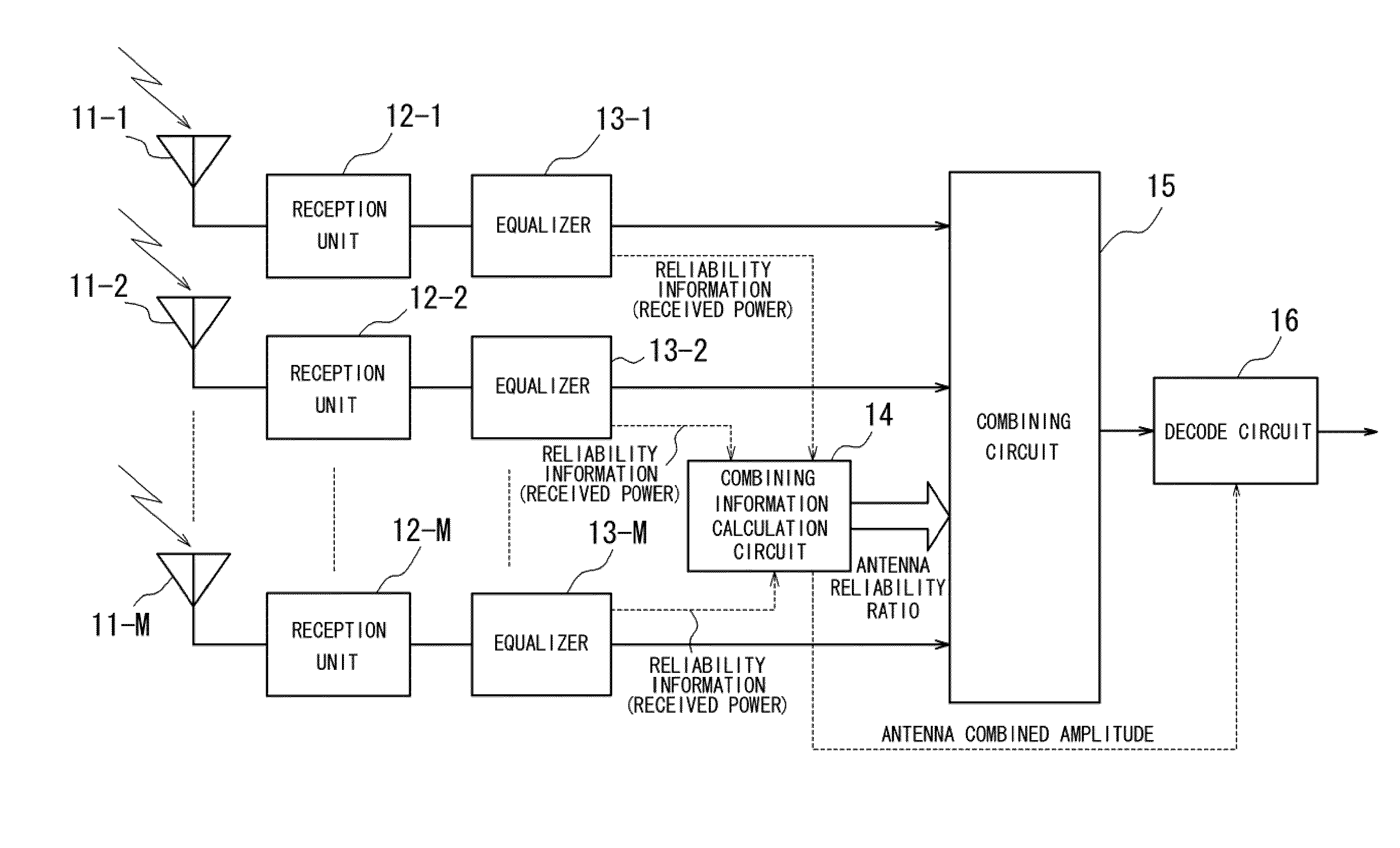
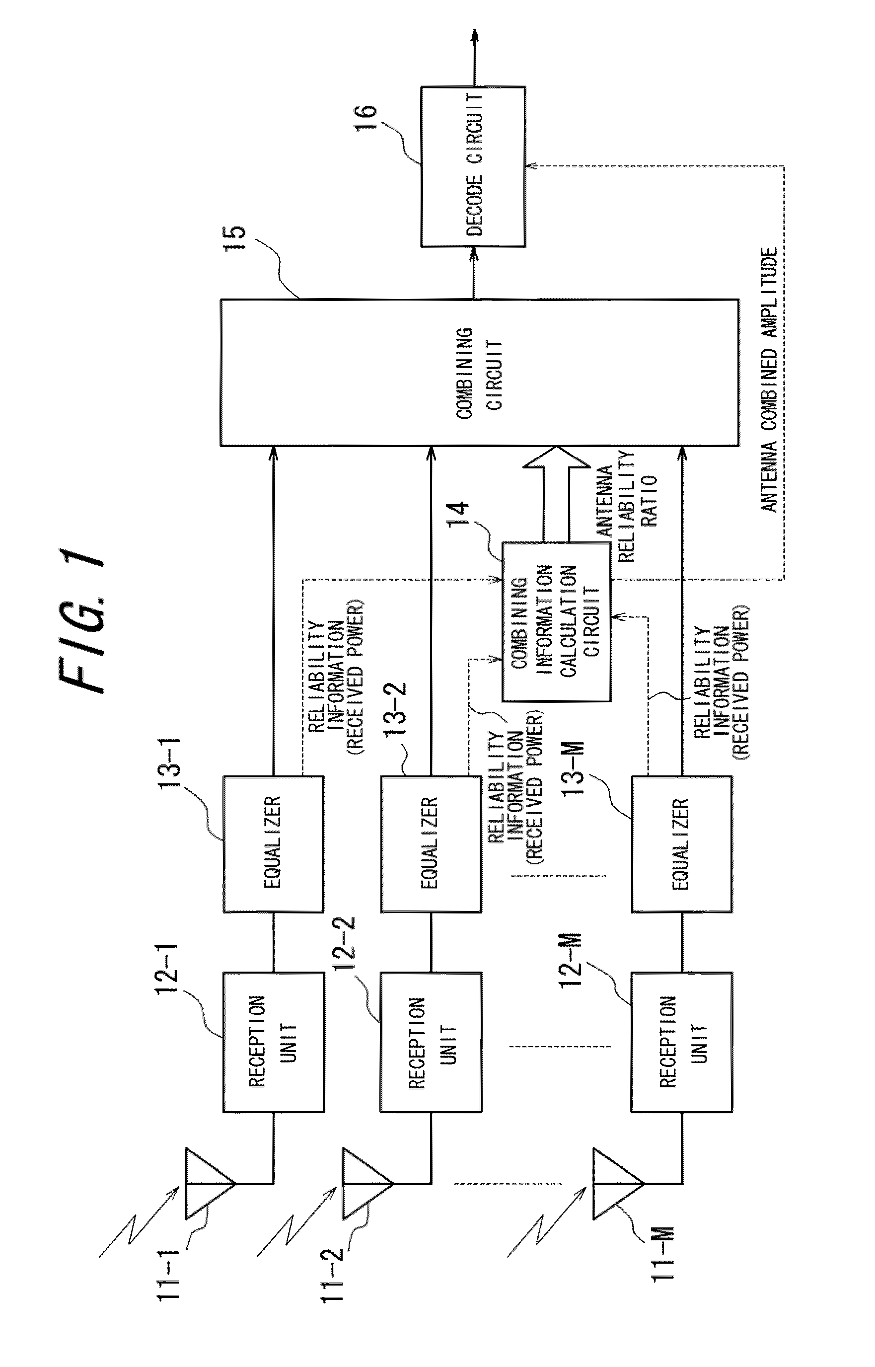
[0049]FIG. 1 is a functional block diagram illustrating a schematic configuration of a main part of a wireless communication apparatus according to an embodiment of the present invention. This wireless communication apparatus is provided with a plurality of antennas 11-1 to 11-M, reception units 12-1 to 12-M and equalizers 13-1 to 13-M which are corresponding to the antennas 11-1 to 11-M, a combining information calculation circuit 14, a combining circuit 15, and a decode circuit 16.

[0050]Arrival signals received by the antennas 11-1 to 11-M are reception-processed and A / D converted by the corresponding reception units 12-1 to 12-M, and then output. Output signals from the reception units 12-1 to 12-M are provided to the equalizers 13-1 to 13-M respectively.

[0051]Amplitude and phase of the arrival signals received by the antennas 11-1 to 11-M vary by influence of a multipat...


PUM


Abstract

A wireless communication apparatus, having a plurality of antennas 11-1 to 11-M and for diversity-combining signals received by the plurality of antennas 11-1 to 11-M, is provided with a combining information calculation unit 14 for calculating antenna combined amplitude and combining weights based on received power of the plurality of antennas 11-1 to 11-M, a combining unit 15 for weighting and combining the signals received by the plurality of antennas 11-1 to 11-M based on the combining weights calculated, and a decoding processing unit 16 for decoding a combined reception signal generated by the combining unit 15. It thereby improves fading durability of the decoding process by reducing influence of multipath fading caused by arrival waves with delays, even in a case of using only a small number of reception antennas, and maintains a stable reception condition consistently, as well as achieving downsizing of and reduction in cost of hardware.

Description

CROSS REFERENCE TO RELATED APPLICATION[0001]This application claims priority to and the benefit of Japanese Patent Application No. 2007-223198, filed on Aug. 29, 2007, the entire contents of which are incorporated herein by reference.TECHNICAL FIELD[0002]The invention relates to a wireless communication apparatus and a wireless reception method for diversity-combining reception signals using a plurality of antennas.BACKGROUND ART[0003]A mobile wireless communication system generally uses a plurality of antennas so as to increase a reception gain by improving the reception performance at a base station and a mobile terminal station. Here, there is a fading as one of factors which cause deterioration of the reception performance. The fading is a phenomenon in which a radio signal transmitted from the base station or the mobile terminal station turns into multipath signals arriving through a number of paths due to reflection, refraction and scattering by buildings, vehicles, trees and ...

Claims


Application Information

Patent Timeline
Patent Type & Authority Applications(United States)
IPC IPC(8): H04B1/06H04L27/06
CPCH04B7/0865H04B7/0885H04B7/0857
Inventor TOYAMA, DAISUKEKUSANO, YOSHIMASA
Owner KYOCERA CORP
Why Eureka
Try Eureka