Expandable spinal implant apparatus and method of use

a spinal implant and expandable technology, applied in the field of expandable spinal implant apparatus, can solve the problems of thinning of the disc, abnormal movement, and positioning the device in this way not to promote lordosis, and achieve the effects of reducing patient risk, speeding up recovery, and improving success rates

Active Publication Date: 2010-11-11
STRYKER EURO OPERATIONS HLDG LLC
View PDF99 Cites 189 Cited by
  • Summary
  • Abstract
  • Description
  • Claims
  • Application Information

AI Technical Summary

Benefits of technology

[0024]The present invention is constructed to decrease patient risk, speed recovery and substantially improve success rates in terms of restoration of normal spinal confirmation and neurological decompression. This is achieved by providing the surgeon with an expandable spacer ...

Problems solved by technology

These problems include, for example, degeneration, bulging, herniation, thinning of a disc, or abnormal movement, and the pain that is experienced generally is attributable to friction or pressure that inevitably occurs when one adjacent vertebra exerts uneven pressure, or when both adjacent vertebrae exert such pressure, on the disc.
Existing IF techniques fail to enable fine positioning or stable expansion of an implant device with respect to the vertebrae.
Positioning the device in this way does not promote lordosis.
The result may be loss of intervertebral space height and/or less than desirable coronal and/or sagittal alignment of the spine.
Existing IF procedures are further limited in other ways.
In existing IF techniques, this requires extensive cutting and/or manipulation of this region, which can extend patient recovery time and subject the patient to other side effects, such as, for example, inflammation, which can be discomf...

Method used


Image

  • Expandable spinal implant apparatus and method of use
  • Expandable spinal implant apparatus and method of use
  • Expandable spinal implant apparatus and method of use

Examples


first embodiment

[0049]an expandable spacer 10 of the present invention is shown in FIGS. 4-11. The spacer 10 is shown in FIGS. 4, 6 and 8 prior to expansion, and in FIGS. 5, 7 and 9 in an expanded state. It is to be noted that while the spacer 10 is shown in FIGS. 4-11 in a substantially rectangular shape with a generally curved forward portion, the expandable apparatus of the present invention may come in a range of shapes and sizes. The surgeon may choose a particular spacer size and shape suitable for a given application. The spacer 10 of the present invention is directed to the structural configuration thereof that enables the surgeon to expand the height dimension without any resulting rocking, tilting, slipping, or canting of the spacer 10. The spacer 10 may include one or more on-axis and / or one or more off-axis positioning interface sites. Spacer size, shape and positioning interface site options and examples are described in the present applicant's previously filed provisional application ...

second embodiment

[0061]an expandable spacer 100 depicting this configuration is shown in FIGS. 12-15, wherein elements corresponding to like elements of the expandable spacer 10 have the same identifying numbers. The expandable spacer 100 includes a base component 102, a top component 104 and a height adjuster 106. The base component 102 includes a receiver 108 with dimensions and shape suitable to receive and removably retain the top component 104 there. That is, the external dimensions of the top component 104 are less than the internal dimensions of the receiver 108 of the base component 102. The receiver 108 of the base component 102 further includes a height adjuster port 110, a height adjuster slot 112 and an interior perimeter wall 114. The base component 102 also includes one or more base packing ports 116 extending entirely therethrough at least in the receiver 108 area but not limited thereto. The base component 102 and the top component 104 are configured so that top surface 105 of the to...

third embodiment

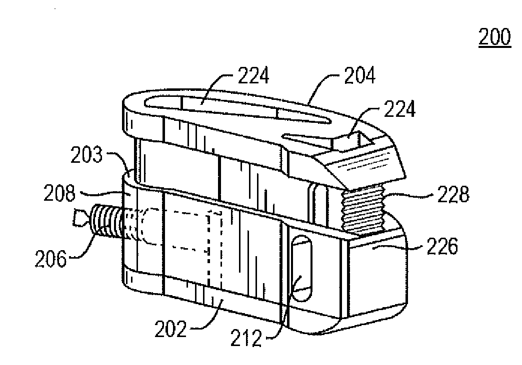
[0069]an expandable spacer 200 is shown in FIGS. 18-23, wherein elements corresponding to like elements of the expandable spacer 10 have the same identifying numbers. The expandable spacer 200 includes a base component 202, a top component 204 and a height adjuster 206. The base component 202 includes a receiver 208 with dimensions and shape suitable to receive and removably retain a portion of the top component 204 there. That is, a portion of the external dimensions of the top component 204 are less than the internal dimensions of the receiver 208 of the base component 202. The top component 204 has a cap 210 that does not fit within the internal dimensions of the receiver 208 (see FIG. 19), and extends over the base component 202. The cap 210 of the top component 204 ends in two beveled surfaces on the opposite end of the spacer 200 from the height adjuster 206. In this embodiment the cap 210 sits on top of the base component 202 over the entire perimeter thereof. However, it is ...


PUM


Abstract

A spinal implant apparatus that is an expandable spacer including features to minimize or eliminate spacer cant or offset during and after completing the expansion process. The spacer includes a top component, a base component in engagement with the top component, and an expansion mechanism arranged to change the top component's position with respect to the base component. The mechanism for causing expansion may be a screw, a cam, a wedge or other form of distracting device. In one embodiment, the expandable spacer includes a base component with a set of towers and a top component with a set of corresponding silos, where the towers and silos are configured to minimize or eliminate tilt of the top component as it extends upwardly from the base component. In another embodiment, the spacer may include a stepped arrangement around the perimeter of the top component and the base component for engagement during height expansion with minimal canting or slippage. In another embodiment, the spacer may include texturing modification at the opposite ends of the longitudinal axis of the spacer to prevent tilting, slipping, or canting. Additionally, a portion of one or more exterior surfaces of the spacer may be textured, sawtoothed, dovetailed or the like to increase frictional intervertebral contact. The spacer may contain one or more passageways of selectable shape/dimension for bone growth through the spacer.

Description

CROSS-REFERENCE TO RELATED APPLICATION[0001]The present invention relates to, and claims priority in, U.S. Provisional Patent Application Ser. No. 61 / 175,918, entitled “EXPANDABLE SPINAL IMPLANT APPARATUS” filed May 6, 2009 by the same inventor. The contents of the related application are incorporated herein by reference.BACKGROUND OF THE INVENTION[0002]1. Field of the Invention[0003]The present invention relates to an expandable spinal implant apparatus and a method of using the apparatus to treat a spine disorder. More particularly, the present invention relates to an intervertebral spacer arranged for expansion of one or more dimensions of the spacer without canting, tilting, or slipping, and methods of using the expandable spacer.[0004]2. Description of the Prior Art[0005]Back pain can be caused by any one of several problems that affect the vertebral discs of the spine. These problems include, for example, degeneration, bulging, herniation, thinning of a disc, or abnormal movem...

Claims


Application Information

Patent Timeline
IPC IPC(8): A61F2/44
CPCA61F2002/4475A61F2002/30782A61F2220/0033A61F2230/0015A61F2230/0086A61F2250/0009A61F2/44A61F2/4455A61F2/4465A61F2002/2835A61F2002/30133A61F2002/30281A61F2002/30354A61F2002/3037A61F2002/30372A61F2002/30377A61F2002/30387A61F2002/30507A61F2002/30518A61F2002/3052A61F2002/30556A61F2002/30579A61F2002/30604A61F2002/30774A61F2220/0025A61F2002/30367A61F2002/30593A61F2/442A61F2/4611A61F2002/30535A61F2/30771
Inventor THIBODEAU, LEE L.
Owner STRYKER EURO OPERATIONS HLDG LLC
Why Eureka
Try Eureka