Fec frame structuring device and fec frame structuring method

a frame structure and frame technology, applied in the direction of code conversion, error correction/detection using convolutional codes, code conversion, etc., can solve the problems of undesired increase in processing speed by about 3%, power consumption and circuit scale increase, and inability to handle optical interfaces including a plurality of lanes

Active Publication Date: 2010-11-11
MITSUBISHI ELECTRIC CORP
View PDF15 Cites 30 Cited by
  • Summary
  • Abstract
  • Description
  • Claims
  • Application Information

AI Technical Summary

Problems solved by technology

In the conventional FEC frame structuring devices and methods, the method using an OTUk frame assumes an optical interface of one wavelength and thus cannot handle optical interface including a plurality of lanes.
Furthermore, although the method using the 64B/...

Method used


Image

  • Fec frame structuring device and fec frame structuring method
  • Fec frame structuring device and fec frame structuring method
  • Fec frame structuring device and fec frame structuring method

Examples


first embodiment

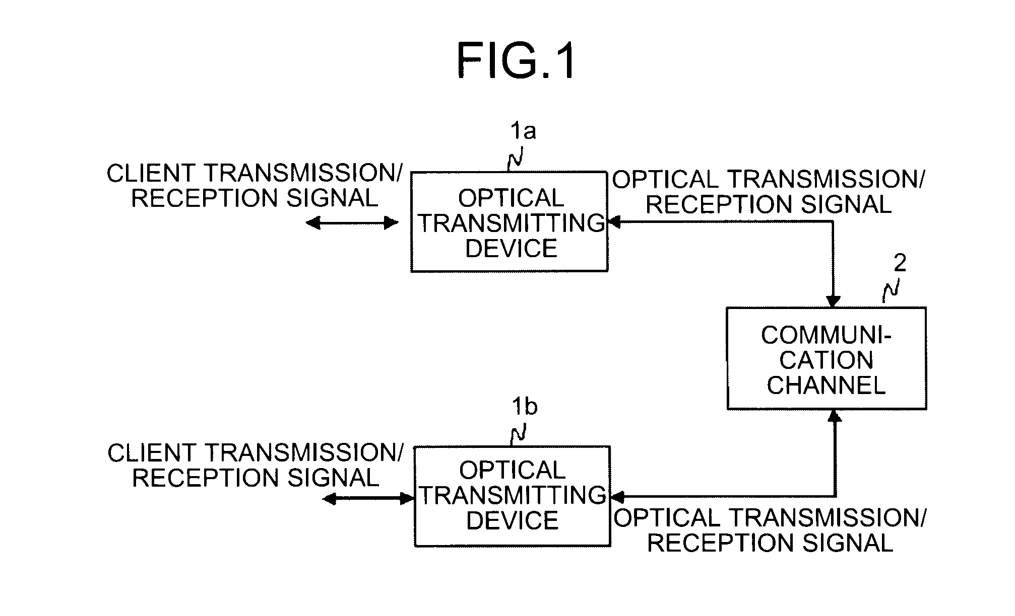
[0022]FIG. 1 is a configuration diagram of a digital communication system (hereinafter, referred to just as an “optical communication system”) that uses an FEC frame structuring device according to the present invention. In the following drawings, like reference numerals denote like or corresponding units. As shown in FIG. 1, optical transmitting devices 1a and 1b perform interconversion of a client transmission / reception signal and an optical transmission / reception signal, such as mapping or demapping of a client signal and an optical transmission frame, error correction coding or decoding, and electrical / optical conversion, so as to provide bidirectional communications between the optical transmitting devices 1a and 1b through a communication channel 2.

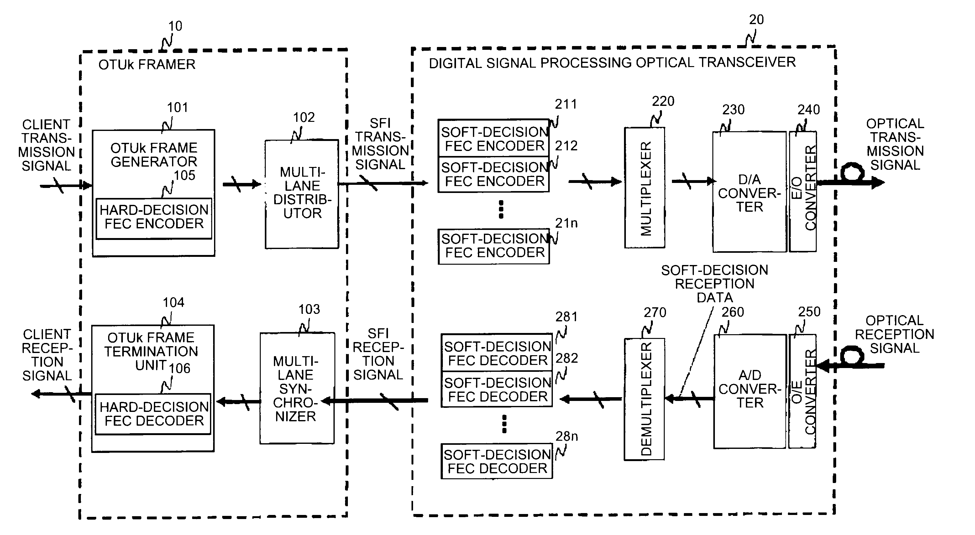
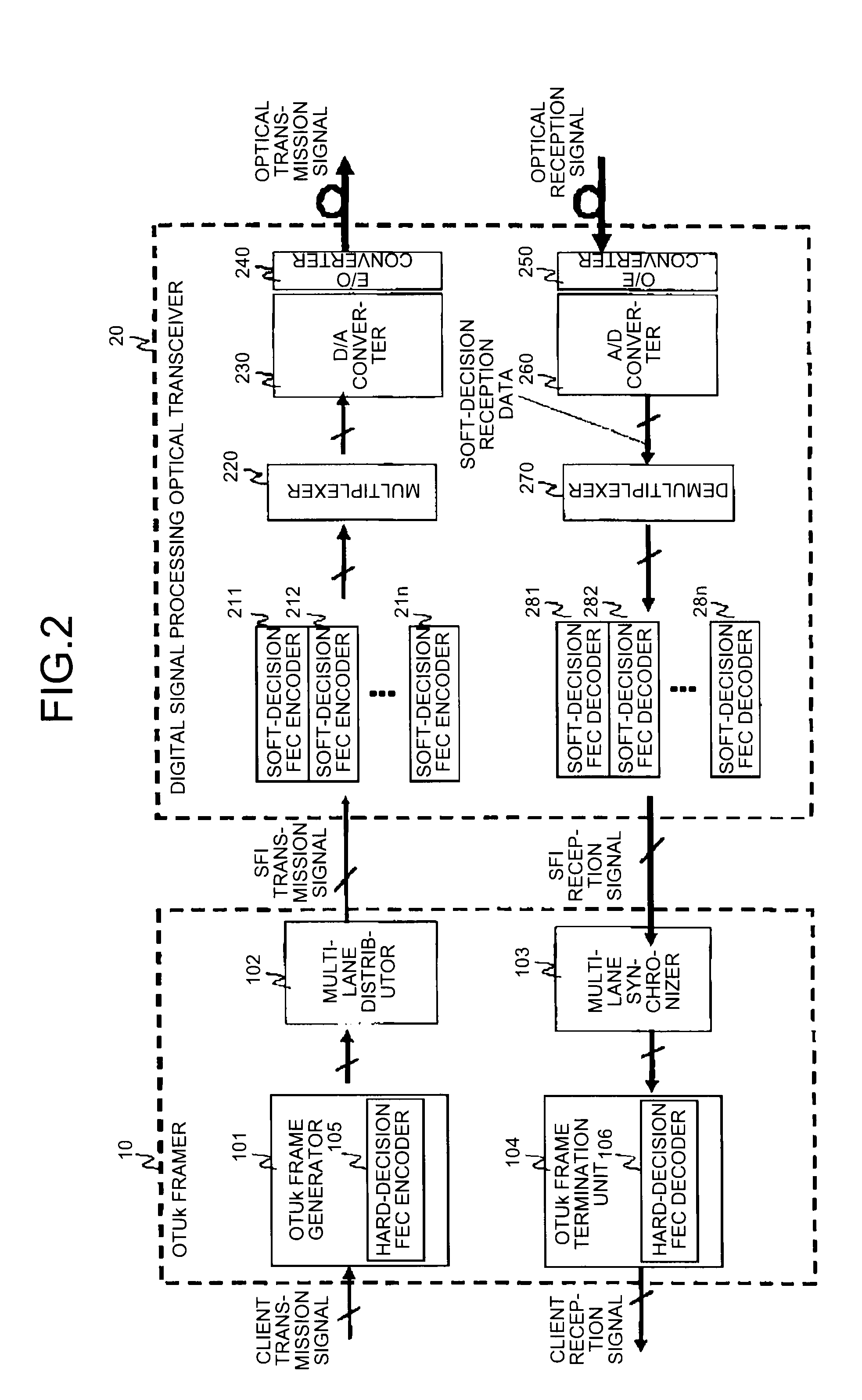
[0023]FIG. 2 is a detailed configuration diagram of the optical transmitting device 1a or 1b shown in FIG. 1. As shown in FIG. 2, an OTUk framer 10 includes an OTUk frame generator 101 that performs mapping of a client transmission ...

second embodiment

[0039]In the second embodiment, the example in which the number of lanes is four and the number of channels for the optical transmission / reception signal is four is described. However, generally, when the number of lanes is n and the number of channels is m, it is required that n be dividable by m (n / m).

[0040]When phase correction between lanes is required for the SFI transmission signal and the SFI reception signal exchanged between the OTUk framer 10 and the digital signal processing optical transceiver 20, multi-lane distributors 102a and 102b and multi-lane synchronizers 103a and 103b are additionally provided as shown in FIG. 7. It is also possible to provide a configuration that uses another phase correcting method for the SFI transmission / reception signals instead of the multi-lane distributors 102a and 102b and the multi-lane synchronizers 103a and 103b.

[0041]In the first and second embodiments, the OTUk frame is distributed to multiple lanes and then the soft-decision FEC ...

third embodiment

[0043]In the third embodiment, the example in which the number of lanes is four and the number of channels for the optical transmission / reception signal is four is described. However, generally, when the number of lanes is n and the number of channels is m, then it is required that n be dividable by m (n / m).

[0044]When correction of phases among lanes is required in the SFI transmission signal and the SFI reception signal exchanged between the OTUk framer 10 and the digital signal processing optical transceiver 20, the multi-lane distributors 102a and 102b and the multi-lane synchronizers 103a and 103b may be additionally provided as shown in FIG. 9. It is also possible to provide a configuration that uses another phase correcting method for the SFI transmission / reception signals instead of the multi-lane distributors 102a and 102b and the multi-lane synchronizers 103a and 103b.

[0045]In the first and second embodiments, the example in which the FEC coding and decoding processes are ...


PUM


Abstract

An FEC frame structuring device includes a multi-lane distributing unit that distributes a data frame to be transmitted to n lanes, FEC coding units each performs FEC coding of the distributed data frame independently for each of the n lanes to generate an FEC frame, a multiplexing unit that multiplexes the FEC frame from the FEC coding units by relating to m channels of an optical signal, a demultiplexing unit that demultiplexes the m channels of the received optical signal by relating to the n lanes, FEC decoding units each performs FEC decoding of the demultiplexed FEC frame independently for each of the n lanes, and a multi-lane synchronizing unit that synchronizes the n lanes with each other after the FEC decoding performed by the FEC decoding units to reconstruct the original data frame.

Description

BACKGROUND OF THE INVENTION[0001]1. Field of the Invention[0002]The present invention relates to a frame structuring device and a frame structuring method in which FEC (Forward Error Correction) applied to a digital communication device such as an optical communication system is used.[0003]2. Description of the Related Art[0004]In conventional FEC frame structuring devices and methods, a method in which a Reed-Solomon (RS) error correction code is used in an OTUk (Optical channel Transport Unit-k) frame is applied (see, for example, ITU-T Recommendation G.709).[0005]Another method is also proposed in which an OTUk frame is distributed to four lanes by using a 64B / 66B transmission code so as to be transmitted by an optical interface including four wavelengths (see, for example, OIF-VSR5-01.0).[0006]In the conventional FEC frame structuring devices and methods, the method using an OTUk frame assumes an optical interface of one wavelength and thus cannot handle optical interface includ...

Claims


Application Information

Patent Timeline
IPC IPC(8): H03M13/05G06F11/10
CPCH03M13/253H03M13/2792H04J3/1652H03M13/1102H03M13/1515H03M13/152H03M13/23H03M13/2906H03M13/2933H03M13/2936H03M13/2966H04J2203/0089H04L1/0041H04L1/0065H04L2001/0096
Inventor KUBO, KAZUOMIZUOCHI, TAKASHISUGIHARA, TAKASHI
Owner MITSUBISHI ELECTRIC CORP
Why Eureka
Try Eureka