
Cable suspended pumping system

Inactive Publication Date: 2010-11-18
ZEITECS
View PDF29 Cites 60 Cited by
  • Summary
  • Abstract
  • Description
  • Claims
  • Application Information

AI Technical Summary

Benefits of technology

[0006]In another embodiment, pumping system includes: a submersible electric motor operable to rotate a drive shaft; a pump rotationally fixed to the drive shaft; an isolation device operable to expand into engagement with a casing string, thereby fluidly isolating an inlet of the pump from an outlet of the pump and rota...

Problems solved by technology

There has been limited deployment of cable inserted in coil tubing where the coiled tubing is utilized to support the weight of the equipment and cable, although this system is seen as an improvement over jointed tubing the cost, reliability and availability of coiled tubing units have prohibited use on a broader basis.

Method used


Image

  • Cable suspended pumping system
  • Cable suspended pumping system
  • Cable suspended pumping system

Examples


Embodiment Construction

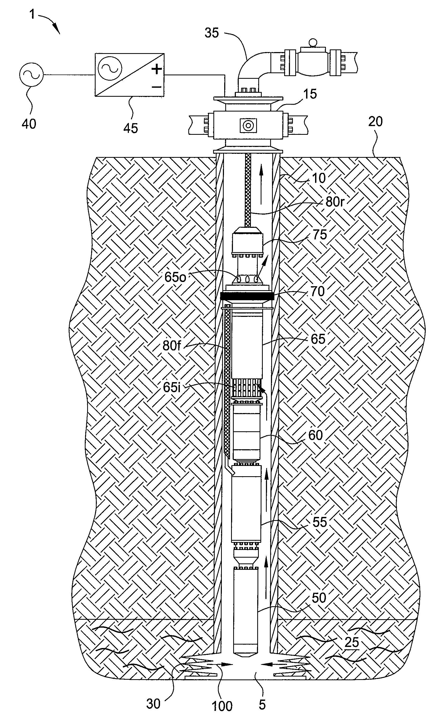
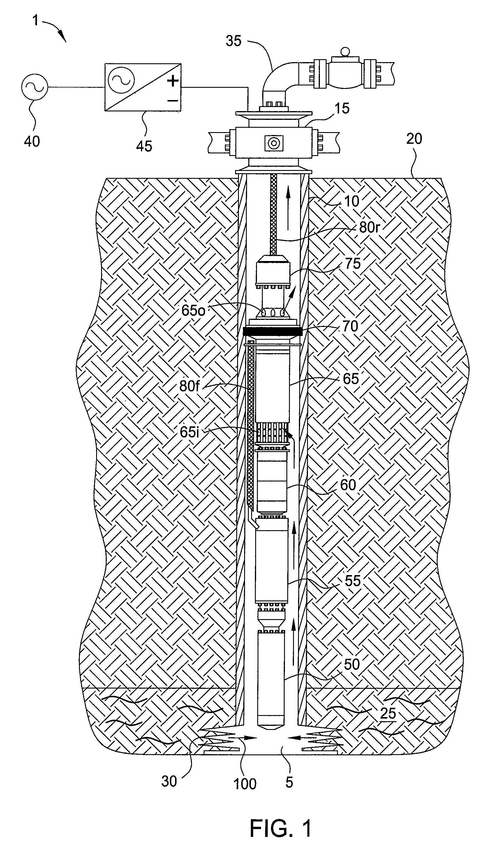
[0010]FIG. 1 illustrates an ESP system 1 deployed in a wellbore 5, according to one embodiment of the present invention. The wellbore 5 has been drilled from a surface of the earth 20 or floor of the sea (not shown) into a hydrocarbon-bearing (i.e., crude oil and / or natural gas) reservoir 25. A string of casing 10 has been run into the wellbore 5 and set therein with cement (not shown). The casing 10 has been perforated 30 to provide to provide fluid communication between the reservoir 25 and a bore of the casing 10. A wellhead 15 has been mounted on an end of the casing string 10. An outlet line 35 extends from the wellhead 15 to production equipment (not shown), such as a separator. Alternatively, the casing 10 may be lined by a removable production liner (not shown) to protect the cemented casing from corrosion by the reservoir fluid 100.

[0011]The ESP system 1 may include a surface controller 45, an electric motor 50, a power conversion module (PCM) 55, a seal section 60, a pump ...


PUM


Abstract

Embodiments of the present invention generally relate to a cable suspended pumping system. In one embodiment, a method of producing fluid from a reservoir includes deploying a pumping system into a wellbore to a location proximate the reservoir using a cable. The pump assembly includes a motor, an isolation device, a pump, and a power conversion module (PCM). The method further includes setting the isolation device, thereby rotationally fixing the pumping system to a tubular string disposed in the wellbore and isolating an inlet of the pump from an outlet of the pump; supplying a DC power signal from the surface to the PCM via the cable; and supplying a second power signal to the motor, thereby operating the pump and pumping reservoir fluid from the reservoir to the surface.

Description

BACKGROUND OF THE INVENTION[0001]1. Field of the Invention[0002]Embodiments of the present invention generally relate to a cable suspended pumping system.[0003]2. Description of the Related Art[0004]The oil industry has utilized electric submersible pumps (ESPs) to produce high flow-rate wells for decades, the materials and design of these pumps has increased the ability of the system to survive for longer periods of time without intervention. These systems are typically deployed on the tubing string with the power cable fastened to the tubing by mechanical devices such as metal bands or metal cable protectors. Well intervention to replace the equipment requires the operator to pull the tubing string and power cable requiring a well servicing rig and special spooler to spool the cable safely. The industry has tried to find viable alternatives to this deployment method especially in offshore and remote locations where the cost increases significantly. There has been limited deploymen...

Claims


Application Information

Patent Timeline
IPC IPC(8): E21B43/12E21B47/00F04B47/08F04B49/00
CPCF04B47/02E21B43/128E21B47/008
Inventor FIELDER, LANCE I.WORRALL, ROBERT NICHOLAS
Owner ZEITECS
Learn More