Power supply system

Active Publication Date: 2010-11-18
MITSUBISHI ELECTRIC CORP
View PDF9 Cites 29 Cited by
  • Summary
  • Abstract
  • Description
  • Claims
  • Application Information

AI Technical Summary

Benefits of technology

[0008]The present invention has an object of providing a power supply system capable of solving the above-discussed problems, properly addressing other faults including the short circuit fault of a DC converter, as well as capa

Problems solved by technology

However, in such an arrangement in which high-voltage system and low-voltage system are connected together via a DC converter, in the case of occurrence of any fault in the DC converter, not only power feed to an electric load in the low-voltage system cannot continue, but also the breakdown of an electric load in the low-voltage system may be induced.
In the case of occurrence of these fault modes at the DC converter, since an electric power of not less than a rating is applied to an electric load or a power source apparatus in the low-voltage system, this case likely

Method used


Image

  • Power supply system
  • Power supply system
  • Power supply system

Examples


embodiment 1

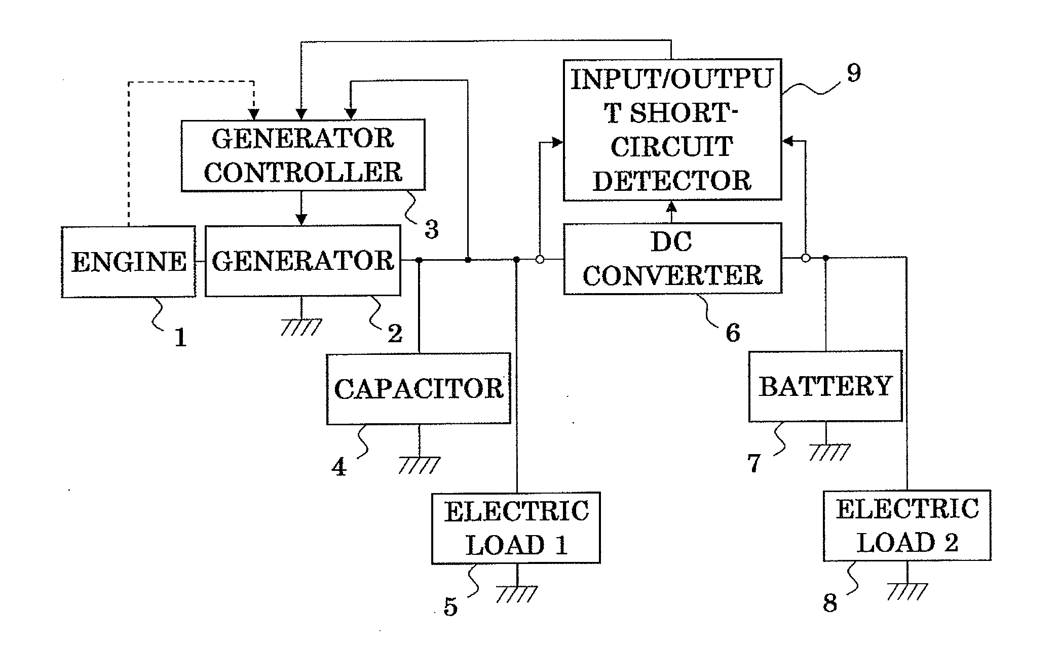
[0041]A first preferred embodiment according to the present invention is hereinafter described referring to the drawings. In the drawings, reference numeral 1 designates an engine generating a power of vehicles, numeral 2 designates a generator that is connected to the engine to generate an electric power, numeral 3 designates a generator controller acting to control the amount of power generated at the generator based on an output voltage of the generator, numeral 4 designates a capacitor acting to charge an electric power having been generated at the generator, numeral 5 designates an electric load 1 to operate by an electric power having been generated at the generator, numeral 6 designates a DC converter acting to convert an electric power having been generated at the generator, numeral 7 designates a battery acting to charge an electric power having been converted at the DC converter, numeral 8 designates an electric load 2 to operate by an electric power having been converted ...

embodiment 2

[0047]A second embodiment according to the present invention is hereinafter described with reference to FIG. 5. In the drawings, the same reference numerals designate like parts as in FIG. 1. Reference numeral 10 designates an output over-voltage detector detecting output over-voltage of the DC converter 6, and from result of the detection, giving an instruction to the generator controller 3.

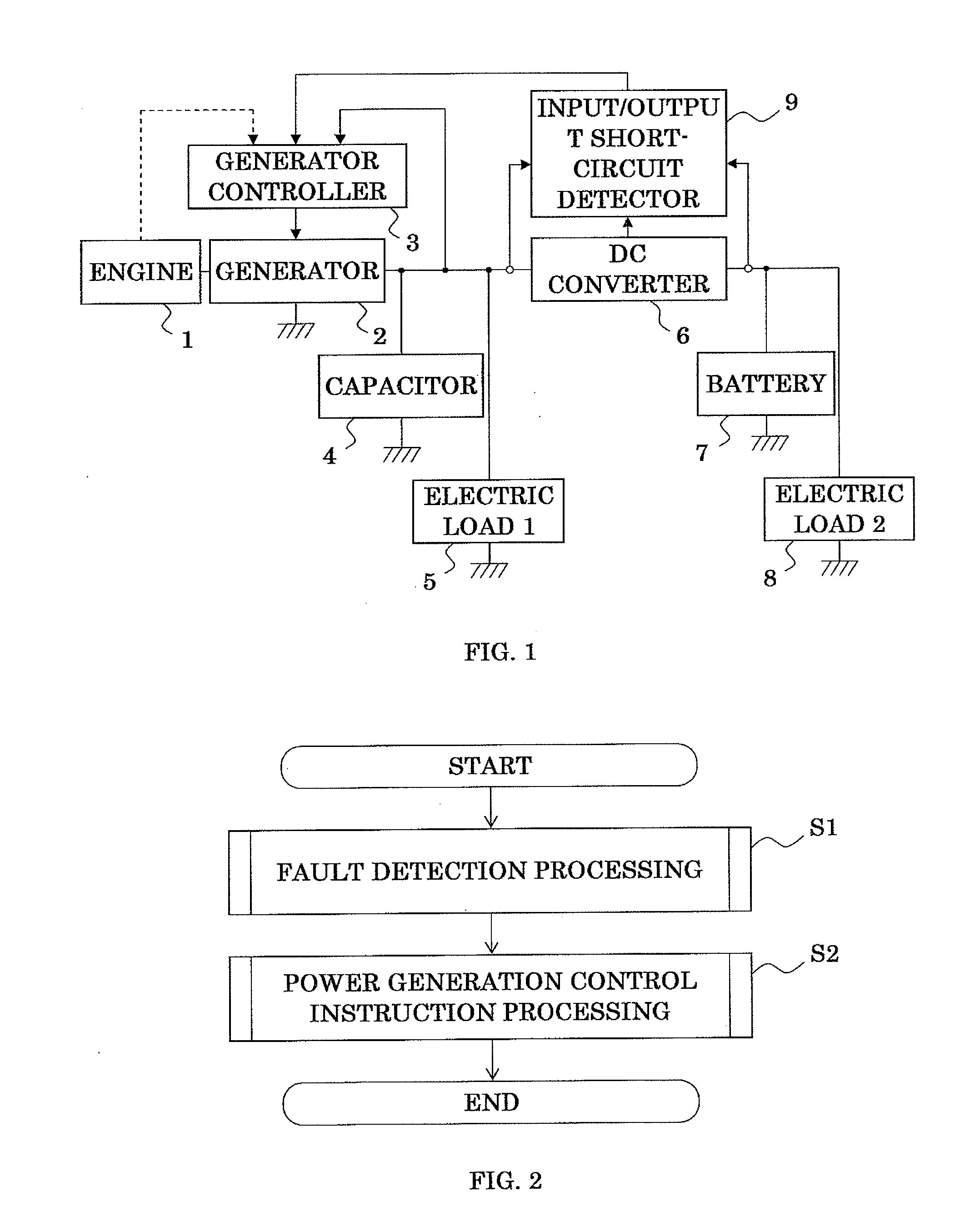
[0048]Now, operations are described. In this embodiment, the schematic processing procedure of the above-mentioned output over-voltage detector 10 is the same as in the procedure shown in FIG. 2 of the first embodiment, and is a basic concept common to that of other embodiments. FIG. 6 is a flowchart showing the schematic processing procedure of fault detection processing. In this embodiment, comparison is made between an output voltage Vout and a predetermined threshold Vth of the DC converter 6 (S11), and in the case that the output voltage Vout is larger than the above-mentioned threshold Vth...

embodiment 3

[0052]A third embodiment according to the present invention is hereinafter described with reference to FIG. 9 showing a processing schematic diagram of this embodiment. In the drawings, the same reference numerals designate like parts as in FIG. 1. Reference numeral 11 designates an output over-current detector detecting output over-current of the DC converter 6, and from results thereof, giving an instruction to the generator controller 3.

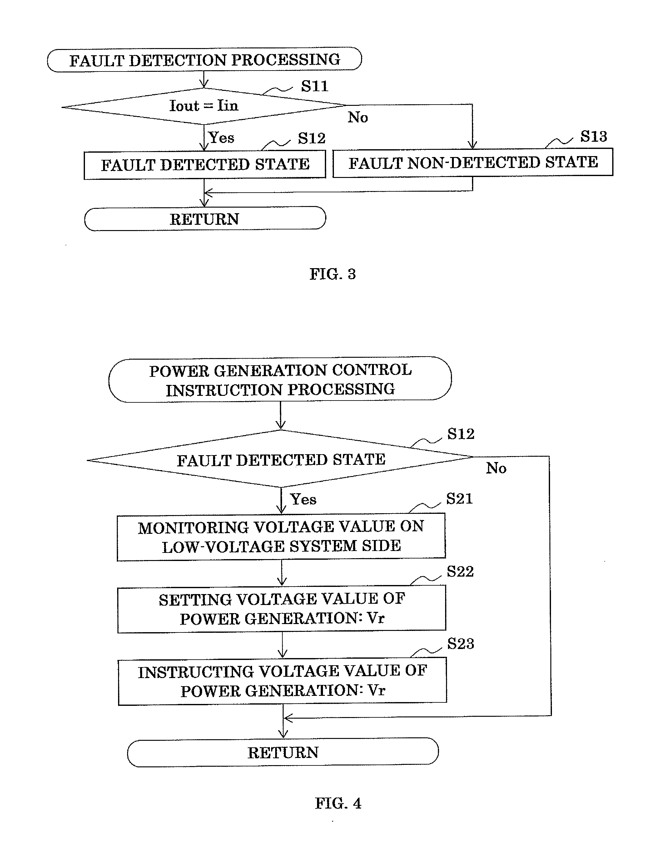
[0053]Now, operations are described. FIG. 10 is a flowchart of showing the schematic processing procedure of fault detection processing. In this embodiment, comparison is made between an output current lout from the DC converter and a predetermined threshold Ith (S11), and in the case that the output current lout is larger than the threshold Ith, the output from the DC converter is determined to be in over-current and it is set to be in the state of fault detection (S12). In the case that the output current lout from the DC converter is not more t...


PUM


Abstract

A power supply system is provided with devices of generating an electric power, controlling an amount of power generation, charging an electric power having been generated, converting an electric power having been generated, charging an electric power having been converted, operating an electric load by an electric power having been converted, and detecting a short-circuit fault of input/output of a DC converter. In the case of detecting an input/output short-circuit fault of the DC converter, from the input/output short-circuit detector to the generator controller, an instruction is given such that the generator is switched to make a power generation at a predetermined constant voltage determined based on a voltage of the circuit arrangement.

Description

BACKGROUND OF THE INVENTION[0001]1. Field of the Invention[0002]The present invention relates to a power supply system having two charge systems and, more particularly, to a power supply system that can continue to supply an electric power to an electric load or a power source apparatus of vehicles even on the occasion of occurrence of any fault in components.[0003]2. Description of the Related Arts[0004]In hybrid cars or idling stop cars, as compared with conventional engine cars, it is necessary to charge a more electric power. Therefore, an arrangement has been proposed, and in which a generator is made to be of high output, a generated power thereof is charged in a high-voltage battery, and an electric power having been generated by this high-output generator is fed to an electric load in a low-voltage system of vehicles via a DC converter.[0005]However, in such an arrangement in which high-voltage system and low-voltage system are connected together via a DC converter, in the c...

Claims


Application Information

Patent Timeline
IPC IPC(8): H02J9/00
CPCH02J7/1423Y02T10/7022Y02T10/7005H02J7/1461Y02T10/70H02J7/00308H02J7/00309H02J7/0047H02J7/00304
Inventor SUGITA, HIDEKI
Owner MITSUBISHI ELECTRIC CORP
Why Eureka
Try Eureka