Electrical linear motor for propulsion of marine vessel

a technology of electric linear motors and marine vessels, applied in the direction of propulsive elements, dynamo-electric machines, water-acting propulsive elements, etc., can solve the problems of linear bearings and thruster sub-assembly contact areas that are more susceptible to wear and more easily detected vessels, and achieves a small water resistance, increase the resulting axial linear propelling force, and reliable operation. long-lasting

Inactive Publication Date: 2010-11-18
KOTLYAR OLEG
View PDF2 Cites 8 Cited by
  • Summary
  • Abstract
  • Description
  • Claims
  • Application Information

AI Technical Summary

Benefits of technology

[0007]An advantage of the present invention is an electrical linear motor compact design that results in a single axial propelling force, vector of which coincides with the thruster subassembly longitudinal axis, thereby excluding a radial load on linear ball bearings and therefore providing more reliable and long-lasting operational life span for the electrical linear motor marine propulsion system.
[0008]Another advantage of new invention is that the increase of the resulting axial linear propelling force can be done by increase of the amount of electrical coil windings 3 (FIG. 1) placed in the electrical linear motor insert 2, and corresponding number of permanent magnets sets 4 installed on the magnet holder 12 without any change of insert outside diameter. For that purpose the geometry of the linear motor insert 2 (FIG. 1) internal space passage—place for thruster subassembly reciprocating movement—and also thruster subassembly permanent magnets holder 12 (FIG. 1) outside geometry have to be an equilateral triangular (case for 3 sets of electrical coil windings and magnets; FIG. 3), square (case for 4 sets of electrical coil windings and magnets; FIG. 4) pentagonal (case of 5 sets of electrical coil windings and magnets; FIG. 5). The amount of windings and magnets sets depends on how big the insert maximum outside diameter can be selected for each project.SUMMARY OF THE INVENTION
[0009]Aspects of the invention relate to employment of the new electrical linear motor propulsion system to propel an object through a medium such as water. One aspect of the invention comprises an electrical linear motor(s) within a cylindrical housing, which is secured to the vessel and submerged in the water. Two covers (one cover on each housing butt end) are connected to the housing. Each cover has a linear ball bearing, o-ring and cuff seal protecting an inner housing compartment against invasion of dirt and water from the environment. An insert within in the inner housing of the water protected compartment, has a U-shaped cross section with space passage for reciprocating movement of magnets, attached to movable linear motor rotor-thruster subassembly. Linear motor coil windings within the housing are disposed on the insert internal passage walls and are positioned parallel to the longitudinal insert axis along the insert axial length. The electrical linear motor rotor-thruster subassembly performs controllable reciprocating movement between the electrical coil windings located on the insert internal passage walls. The thruster subassembly cylindrical parts move inside of two linear bearings, which in its turn are placed into the two butt-end covers. The permanent magnets are maintained in sufficiently close proximity to the electrical coil windings by two roller restrictors so that an interaction of an electromagnetic field created by the controlled energizing of the electrical coil windings, with a magnetic field from the permanent magnets provides the reciprocal axial force and as a result of action of that force a reciprocal linear motion of the thruster subassembly within the housing. The thruster subassembly having an opposing first and second ends and a check valve installed in the thruster subassembly internal channel, the check valve being in an open position during a back stroke of the thruster subassembly, so that the water flows freely through the thruster subassembly internal channel thereby the thruster has a small water resistance during back stroke. The check valve is in a closed position during a working stroke of the thruster subassembly, so that its front part displaces water with an acting linear force created by the electrical linear motor, and the force of water resistance affects the thruster subassembly and through its magnetic fields, magnets, windings, insert and housing—is transmitted to a vessel hull, thereby propelling the vessel through the water.
[0010]Another aspect of the invention includes various techniques of attaching the new electrical linear motor housing to the vessel, thus giving the propulsion system additional degrees of freedom, thereby increasing maneuverability of the vessel.
[0011]An additional aspect of the invention includes the use of several linear motors of new design to propel a marine vessel, submarine, bathyscaph, torpedo, etc. Two or more linear motors can be attached to a vessel (i.e., rigidly attached, attached by means of a rotating shaft, or rotating coupling hinged attachment). The numerous linear motors are preferably mounted on opposing sides of the vessel's longitudinal axis, with the longitudinal axis each linear motor being parallel to the longitudinal axis of the vessel. Turning a vessel can be accomplished by controlling the propelling force generated by each of the several electrical linear motors.

Problems solved by technology

A disadvantage of utilizing propellers to propel a marine vessel is that the propeller creates a water rotational movement (swirl) in the water, thereby making the vessel more easily detected.
That radial load creates increased friction losses and heat emissions in linear bearings thereby resulting in linear bearings and thruster subassembly contact areas more intensive wear.

Method used


Image

  • Electrical linear motor for propulsion of marine vessel
  • Electrical linear motor for propulsion of marine vessel
  • Electrical linear motor for propulsion of marine vessel

Examples


Embodiment Construction

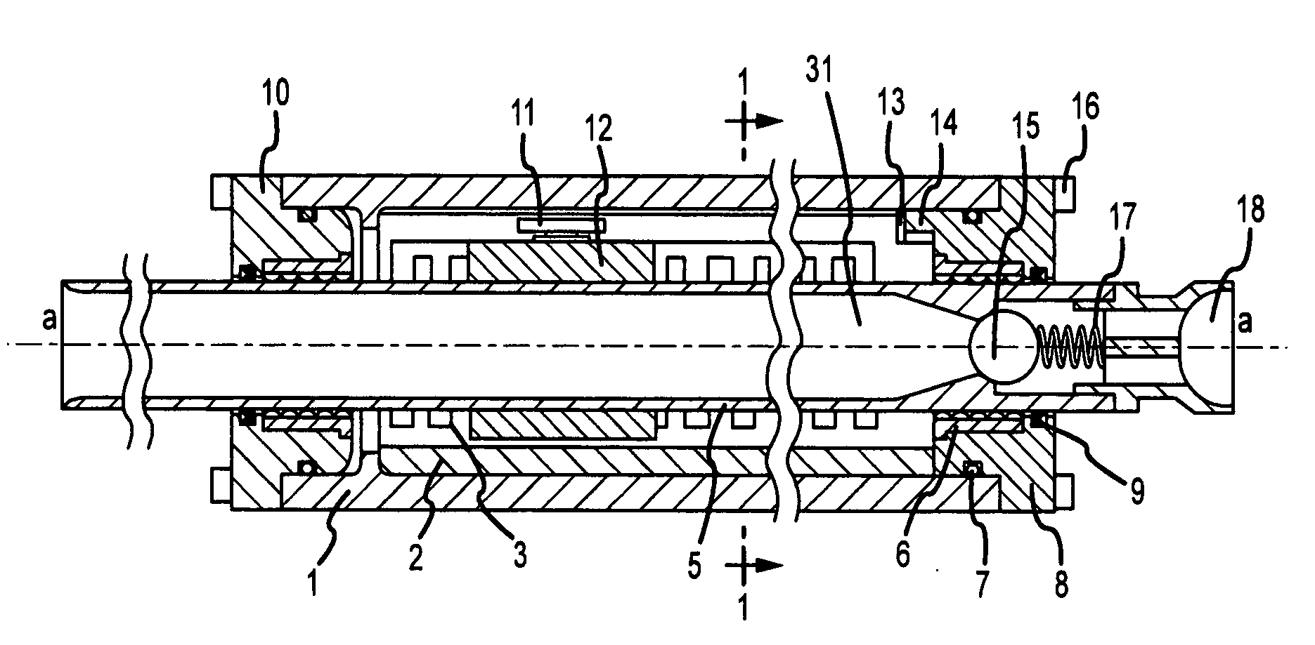
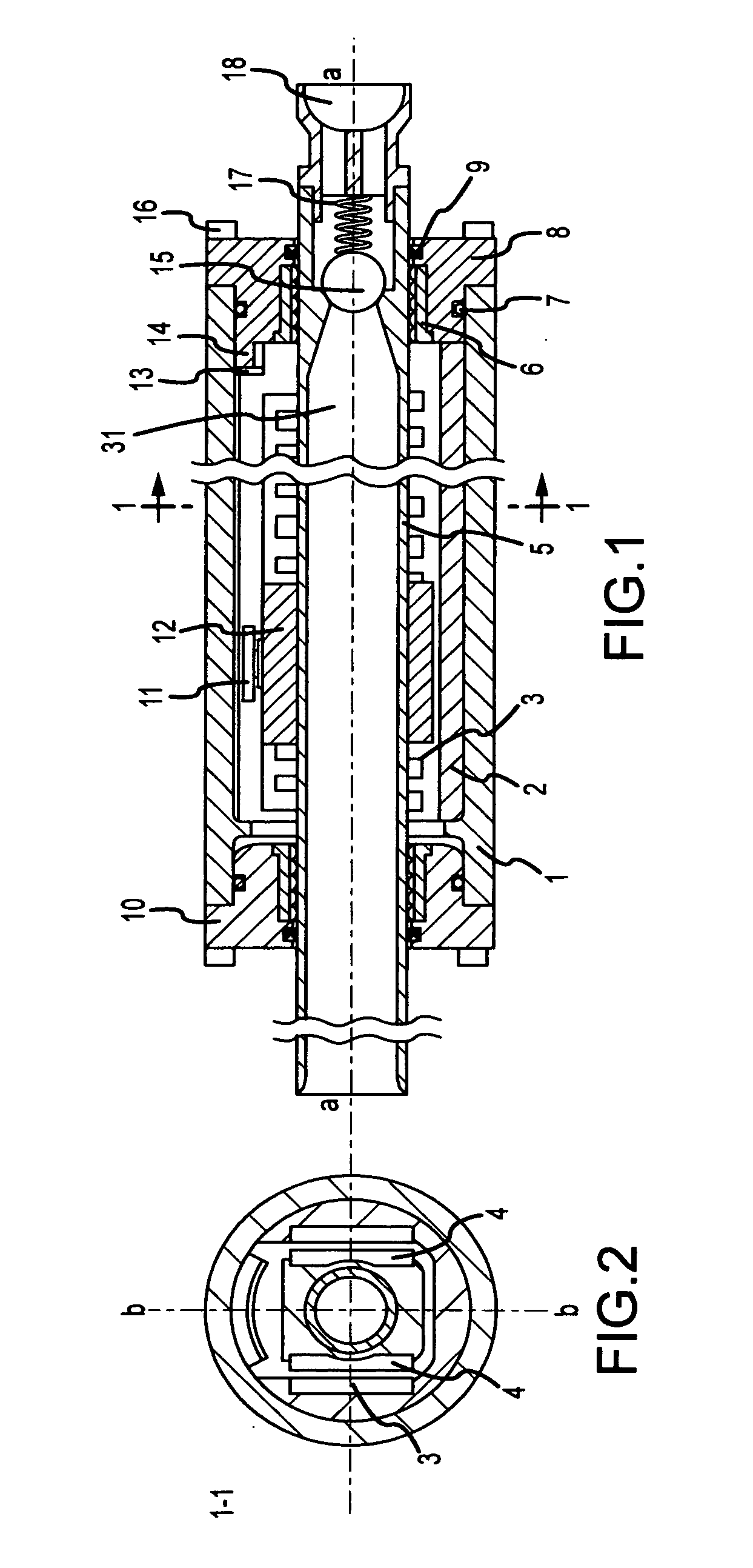
[0017]Referring to FIG. 1 there is disclosed an embodiment of an electrical linear motor with a linear motor cylindrical housing 1. The electrical linear motor housing 1 is submerged in the medium through which an object, such as a vessel, is to be propelled on the water surface or the object could be a submarine or bathyscaphe completely submerged underwater. For purposes of this application, the term “medium will generally hereinafter be referred to as water, it being acknowledged that medium could consist of any liquid material.

[0018]The electrical linear motor housing contains an insert 2 that has a U-shaped cross-section. At least, two electrical windings 3 are disposed on internal vertical walls of the insert 2—one opposite another, but with a space between them. Two sets of magnets 4 are attached to a magnet holder 12 that is secured to the body of a thruster subassembly 5. Thruster subassembly 5 with an internal channel 31, has a longitudinal axis coinciding with the longitu...


PUM


Abstract

An electrical linear motor for propelling a marine vessel through a liquid medium, comprises a housing secured to the marine vessel and submerged in the liquid medium, an insert within the housing and having at least two electrical coil windings disposed on internal walls of the insert; a thruster subassembly moves between the internal walls of the insert, the thruster subassembly having a front cover, an internal channel with check valve and at least two sets of permanent magnets attached to the thruster subassembly and maintained in sufficiently close proximity to the electrical coil windings so that an electromagnetic field created by a controlled energizing of the electrical coil windings interacts with a magnetic field from the permanent magnets to provide a resulting linear force, which causes a reciprocating linear motion of the thruster subassembly, wherein the check valve is in an open position during a back stroke of the thruster subassembly so that the liquid medium flows freely through the thruster subassembly internal channel and wherein the check valve is closed during a working stroke of the thruster subassembly so that the front cover of the thruster subassembly displaces the liquid medium, thereby propelling the marine vessel through the liquid medium.

Description

CROSS-REFERENCE TO RELATED APPLICATIONS[0001]This application claims the benefit of the U.S. Provisional patent application Ser. No. 61 / 271,683 filed Jul. 25, 2009 and is a continuation-in-part application of U.S. Pat. No. 7,604,520 B2, filed Jul. 30, 2007, which is hereby incorporated by reference.TECHNICAL FIELD[0002]The present invention relates to a method and system for propelling an object through a liquid medium, such as water, using an electrical linear motor (ELM).BACKGROUND OF INVENTION[0003]Electrical linear motors are used in various electromechanical actuators. Electrical linear motors are used as well to propel vehicles. For example, linear motors are used in magnetic levitation technology in which train passenger cars float above a concrete guide way and in other high speed “wheels-on-rails” trains. These types of linear motors are usually of the linear synchronous design with an active winding on one side of an air-gap and array of alternate pole magnets on the other...

Claims


Application Information

Patent Timeline
Patent Type & Authority Applications(United States)
IPC IPC(8): B63H21/17
CPCB63H21/17B63H11/06
Inventor KOTLYAR, OLEG
Owner KOTLYAR OLEG
Why Eureka
Try Eureka