Method and apparatus for measuring directionally differentiated (one-way) network latency

a network latency and direction differentiation technology, applied in electrical equipment, transmission, multi-digital computer combinations, etc., can solve the problems of inability to know what portion of the delay is attributable, the failure to efficiently troubleshoot network problems, and the differences in the delay component of network traffi

Inactive Publication Date: 2010-11-18
JOHN FLUKE MFG CO INC
View PDF3 Cites 13 Cited by
  • Summary
  • Abstract
  • Description
  • Claims
  • Application Information

AI Technical Summary

Benefits of technology

[0008]It is a further object of the present invention to provide an improved method of determining directionally differentiated network latency.
[0009]It is yet another object of the present invention to provide an improved test and measurement system for determining directionally differentiated network latency.

Problems solved by technology

However, the delay component of network traffic may differ between upstream and downstream transmission, and such typical techniques provide no knowledge as to what portion of the delay is attributable to upstream and downstream traffic transmission.
Without such knowledge, troubleshooting of network issues is less efficiently accomplished.
Such solutions are expensive, limiting their availability.
However, access to the sky and GPS satellites is problematic in many indoor lab environments, and the equipment is expensive.

Method used


Image

  • Method and apparatus for measuring directionally differentiated (one-way) network latency
  • Method and apparatus for measuring directionally differentiated (one-way) network latency
  • Method and apparatus for measuring directionally differentiated (one-way) network latency

Examples


Embodiment Construction

[0016]The system according to a preferred embodiment of the present invention comprises a system, method and test instrument adapted to determine directional latency in a computer network using native time bases of test devices, without requirement of external time base.

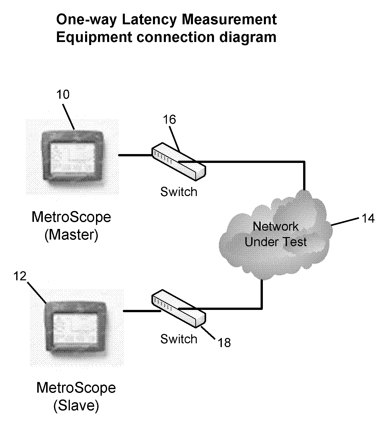
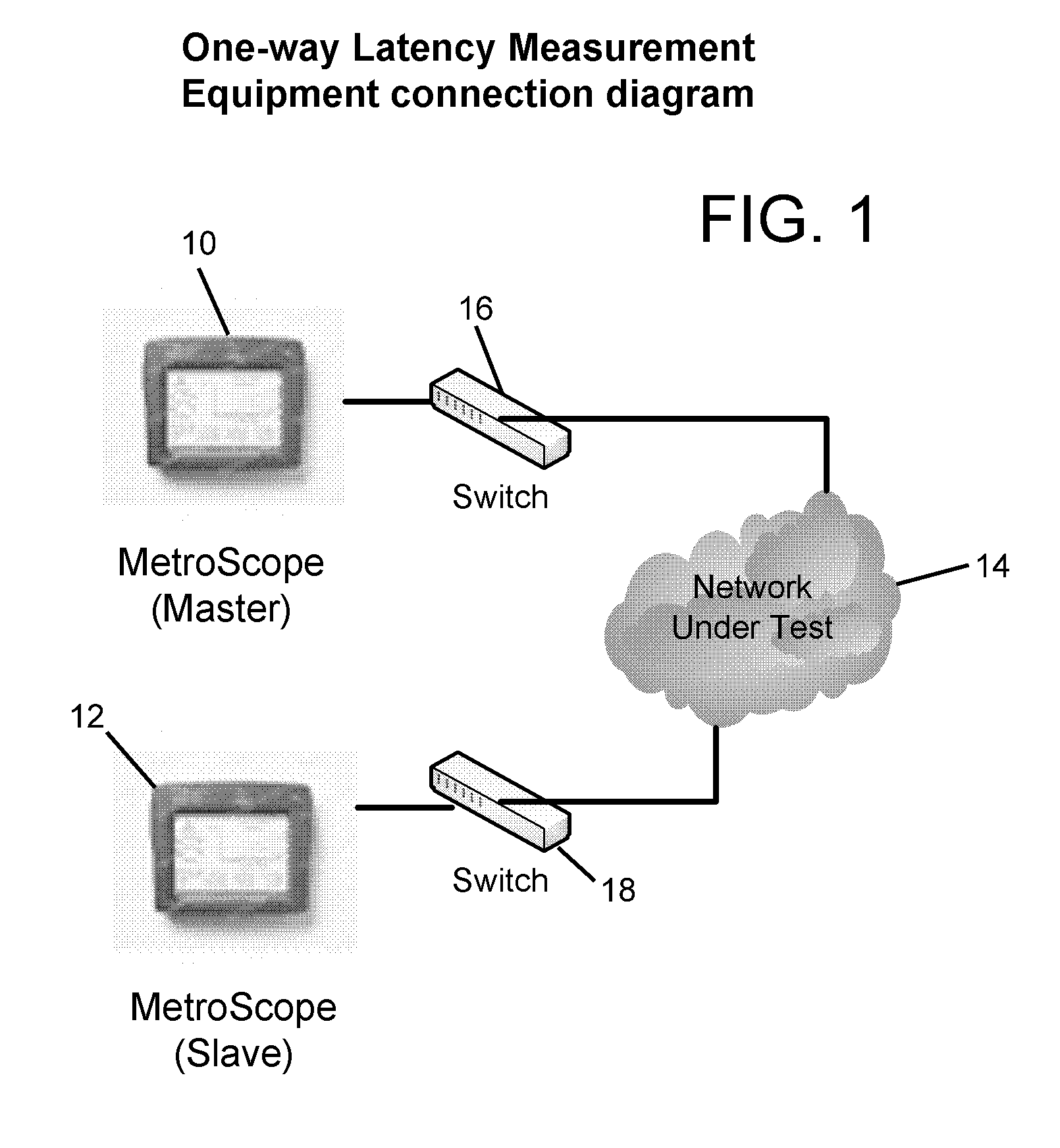
[0017]Referring to FIG. 1, a block diagram of test set up in accordance with directionally differentiated (one-way) latency measurement, in accordance with a preferred embodiment, a master test instrument 10 and slave test instrument 12 are connected to a network under test 14, suitably via switches 16, 18. In the illustrated embodiment, network under test 14 is an Ethernet. Master test instrument 10 and slave test instrument 12 each have their own clocks and are adapted to transmit and receive traffic over the network. The test instruments include processors to operate the instruments to provide network test capability. Suitable test instruments are Fluke MetroScope brand test instruments, by Fluke Corporation, Ever...


PUM


Abstract

Determining directionally differentiated latency in a network by use of master and slave test instruments to record latency measurements in their native time bases, and retrieving test instrument latency frame transmit / receive timestamps from the master and slave and converting them to the time base of one of the master or slave by use of the offset calculation, utilizing 3 bounce timestamp exchange, providing one-way latency measurement with resolution of less than 100 μs, using internal clocks in the test instruments, without requirement of expensive external time base technology.

Description

BACKGROUND OF THE INVENTION[0001]This invention relates to networking test and measurement, and more particularly to network latency measurement.[0002]Network latency is typically measured based on a round trip delay value, by dividing the round trip time of a test message by two. The latency is thus determined based on the time between sending a delay test request to another network station and the time when the reply back from the other station is received.[0003]However, the delay component of network traffic may differ between upstream and downstream transmission, and such typical techniques provide no knowledge as to what portion of the delay is attributable to upstream and downstream traffic transmission. Without such knowledge, troubleshooting of network issues is less efficiently accomplished.[0004]Prior solutions to the desire for determination of one-way latency require use of external time base technology, for example, under IEEE 1588 precision time protocol employing cesi...

Claims


Application Information

Patent Timeline
Patent Type & Authority Applications(United States)
IPC IPC(8): G06F15/16
CPCH04L43/12H04L43/0858
Inventor WITTWER, TIM
Owner JOHN FLUKE MFG CO INC
Why Eureka
Try Eureka