Run-of-river hydroelectric power generation apparatus

a hydroelectric power generation and run-of-river technology, applied in mechanical equipment, electric generator control, machines/engines, etc., can solve the problems of high cost, damage to natural landscape and ecology, and high expense required for building such hydroelectric power generation plants, and achieves low cost, easy installation, and huge installation space

Inactive Publication Date: 2010-11-25
SMART ENERGY
View PDF5 Cites 17 Cited by
  • Summary
  • Abstract
  • Description
  • Claims
  • Application Information

AI Technical Summary

Benefits of technology

[0007]Compared with the prior art, the present invention uses a buoy, an electric generator, a case, a vane wheel and a transmission belt to build a simple-structured run-of-water hydroelectric power generation apparatus that incurs a low cost and provides an easy installation. The invention not just waives the complicated construction and the huge installation space and allows the apparatuses to be installed at different locations of a river without hindering the routes of the boats, but also allows the electric generator to be installed at the water surface to achieve the effects of safe operation and easy maintenance.

Problems solved by technology

However, this method incurs unusually high expenses for the construction of the dam, and the dam also damages the natural landscape and ecology, and thus less and less dams are built now.
However, the expense required for building such hydroelectric power generation plant is very high.
However, the construction of the underwater turbine at the waterbed incurs tremendous efforts and high costs, which are not cost-effective, and the operation of the turbine at the waterbed not only gives rise to a high level of difficulty for the maintenance, but it also has a safety concern.

Method used


Image

  • Run-of-river hydroelectric power generation apparatus
  • Run-of-river hydroelectric power generation apparatus
  • Run-of-river hydroelectric power generation apparatus

Examples


Embodiment Construction

[0013]The technical characteristics and contents of the present invention will become apparent with the following detailed description accompanied with related drawings.

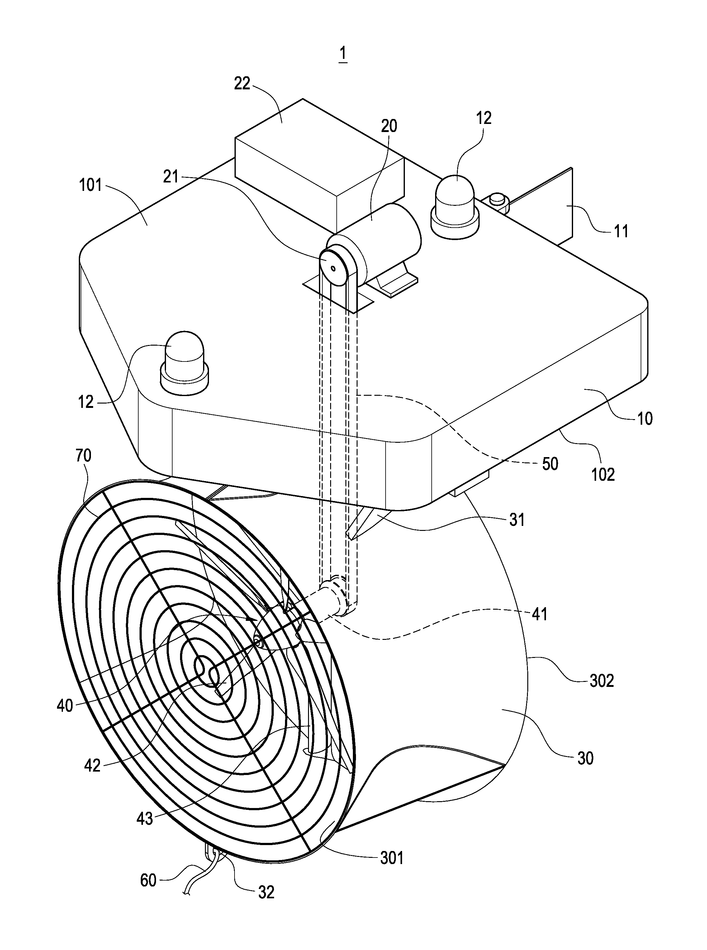
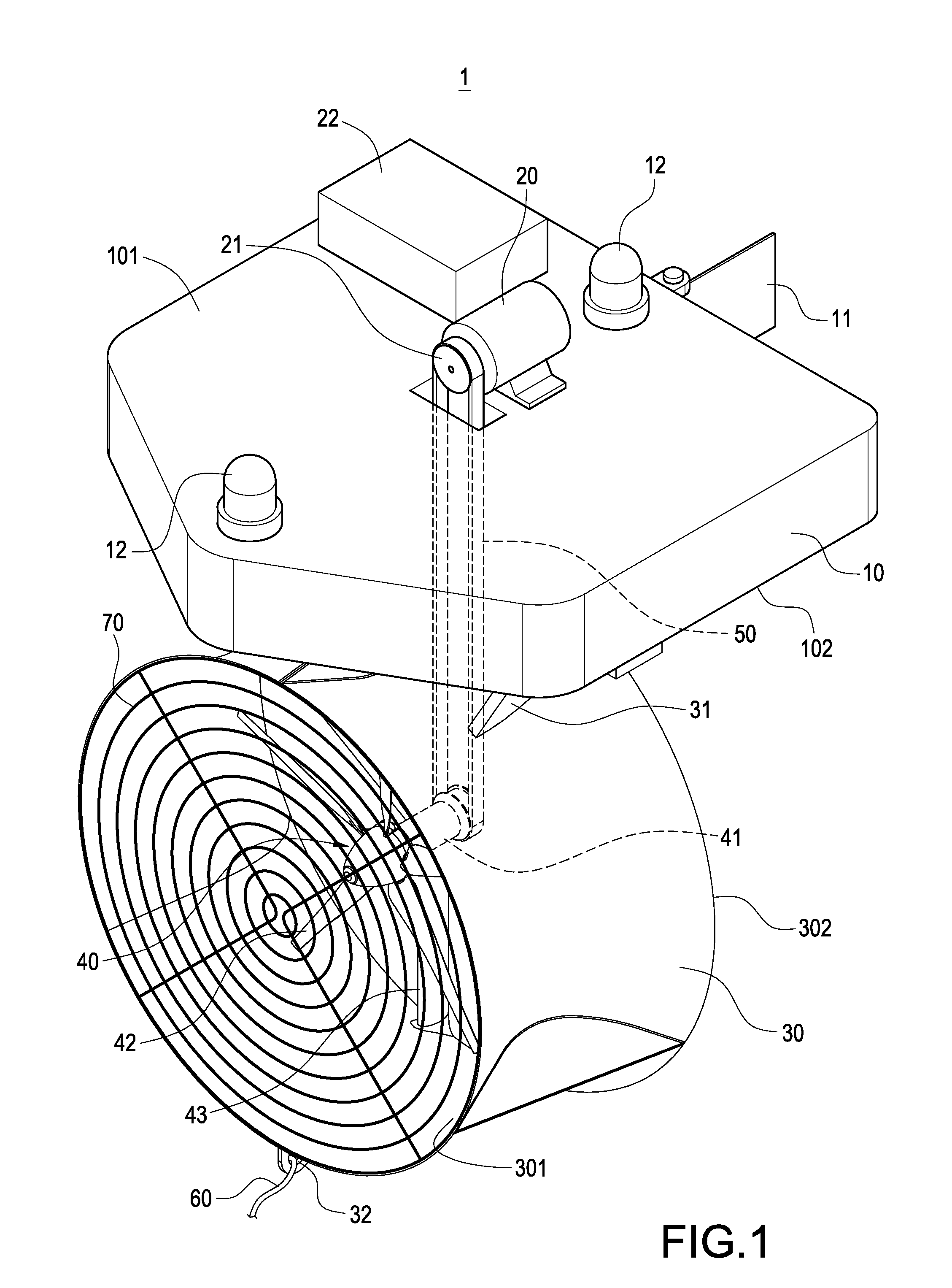
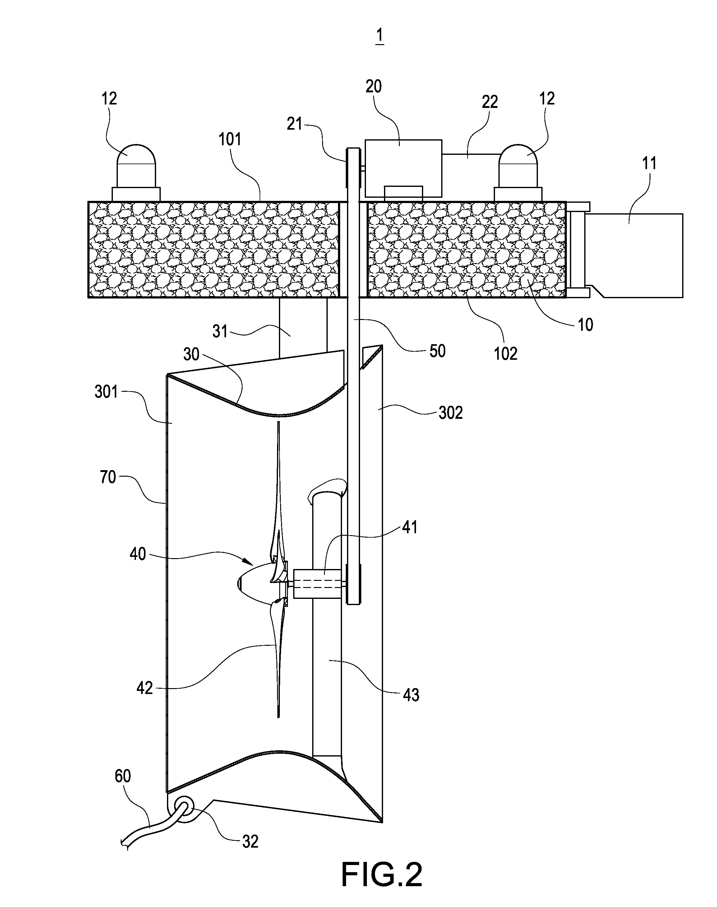
[0014]With reference to FIGS. 1 and 2 for a perspective view and a side view of a run-of-water hydroelectric power generation apparatus in accordance with the present invention respectively, the run-of-water hydroelectric power generation apparatus 1 comprises a buoy 10, an electric generator 20 installed at a top surface of the buoy 10, a case 30 installed at a bottom surface of the buoy 10, and a vane wheel 40.

[0015]The buoy 10 has a buoyancy for floating on a water surface of a flowing water current, and an electric generator 20 is installed at a top surface 101 of the buoy 10 and includes a rotating shaft 21, and the rotating shaft 21 includes a pulley or a gear installed thereon, and a warning lamp 12 is also installed at the top surface 11 of the buoy 10 and connected to the electric generator 20 for alerting a...


PUM


Abstract

A hydroelectric power generation apparatus includes a buoy having a buoyancy for floating on a water surface, an electric generator including a rotating shaft installed at a top surface of the buoy, a hollow case tapered from both ends towards the center of the case, and a side of the case being coupled to the bottom of the buoy and a vane wheel installed at the bottom of the buoy and including a wheel shaft and a plurality of vanes installed in the case, and a transmission belt installed around both wheel shaft and rotating shaft for providing a transmission between the wheel shaft and the rotating shaft, such that when the water current flows through the vanes to drive the wheel shaft to rotate, the transmission of the transmission belt drives the rotating shaft of the electric generator to rotate, so as to generate electric energy.

Description

FIELD OF THE INVENTION[0001]The present invention generally relates to hydroelectric power generation, in particular to a run-of-water hydroelectric power generation apparatus.BACKGROUND OF THE INVENTION[0002]Hydroelectric power generation is a way of generating electric power by converting potential energy and kinetic energy of water into electric energy. At present, there are different methods of achieving the hydroelectric power generation, and one of the methods is to construct a dam and install a hydroelectric generator for the electric power generation. However, this method incurs unusually high expenses for the construction of the dam, and the dam also damages the natural landscape and ecology, and thus less and less dams are built now. Another method is to build a pumped-storage hydroelectric plant including two water storage pools built at upstream and downstream locations of a river respectively. During off-peak hours, water is pumped from the downstream water pool to the ...

Claims


Application Information

Patent Timeline
Patent Type & Authority Applications(United States)
IPC IPC(8): F03B13/00
CPCF03B17/061F05B2240/133Y02E10/38Y02E10/28F05B2260/4021Y02E10/30Y02E10/20
Inventor CHEN, SHIH-HSIUNG
Owner SMART ENERGY
Why Eureka
Try Eureka