Stator coil heating apparatus and stator coil heating method

a stator coil and heating apparatus technology, applied in the direction of induction heating, dynamo-electric machines, packaging, etc., can solve the problems of increasing the temperature of the stator in a slow manner, increasing the cost of electrical energy consumption, and increasing the heating time of the heating process. , to achieve the effect of high cost, and prolonging the heating tim

Inactive Publication Date: 2010-11-25
TOYOTA JIDOSHA KK
View PDF3 Cites 14 Cited by
  • Summary
  • Abstract
  • Description
  • Claims
  • Application Information

AI Technical Summary

Benefits of technology

[0056]According to the invention recited in the item (1), a stator coil is heated by using an induction heating coil head, not by using a hot-air heating furnace. Therefore, a heating time for the process of heating and harden-drying after impregnating a coil with varnish, for example, can be reduced. Furthermore, the inconvenience occurring in the case of harden-drying by a hot-air heating method using a heating furnace, which is the high cost caused due to a longer heating time and more electrical energy consumption, and also environmental inconveniences, are eliminated.
[0057]Furthermore, the inconvenience occurring in the method of energizing the stator coil, which is self-heating temperature variation, is eliminated. And thus, a favorable heating process is enabled.
[0058]Particularly, an end face of a core in the thickness direction thereof is shielded by a shield from a magnetic flux generated by the induction heating coil head. Therefore, the risk that an end face of the core is particularly heated and thermally deformed is eliminated. Furthermore, a large part of a magnetic flux acts on the stator coil accordingly, and the stator coil is efficiently heated and varnish or etc. can be harden-dried rapidly.
[0059]According to the invention recited in the item (2), the shield is provided to the induction heating coil head, in a unified manner. Therefore, the shield can be set at the same time as loading the induction heating coil head, which would contribute to promptness of preparation for heating.
[0060]According to the invention recited in the item (3), the induction heating coil head which diameter is approximately the same as that of the circular winding coil base that is sticking out of each of the end faces of the core in the thickness direction thereof, is used. Therefore, the whole circumference of the winding coil base can be heated at the same time by a magnetic flux generated by the induction coil head, without moving the stator.
[0061]Furthermore, the outer circumference area of an end face of the core in the thickness direction thereof is shielded by the circular shield. Therefore, each of the end faces can be effectively prevented from being thermally deformed.

Problems solved by technology

However, in the method of harden-drying varnish by using a heating furnace, a temperature of the stator is increased in a slow manner after the stator is inserted into a heating furnace.
Therefore, in order to satisfy enough thermal and temporal conditions to harden varnish material, a longer heating time is required and more electrical energy is consumed, which causes high costs.
Furthermore, in order to keep a constant temperature in a heating furnace, a temperature in a heating furnace is required to be increased before inserting a workpiece therein and is required to be kept all the while until entirely discharging a workpiece therefrom, which makes costs still higher.
And accordingly, the stator coil could not be heated favorably, which leaves a problem.
Therefore, this method is not an easy choice and leaves a problem.
However, in the conventional method above, since the stator coil is heated from its surface in a slow manner, a longer heating time is required.
And even trying to heat the stator coil and the core uniformly and evenly, a long heating time is required and keeping the stator coil at a predetermined temperature is not easy.
As results, varnish applied to the stator coil could not be impregnated well and the molding could lose its quality because a crack or etc. could be caused, which leaves a problem.
Since a core is usually constructed of layered silicon steel plates and the thermal conductivity in the thickness direction of such a core is low, only these parts are particularly heated and thereby thermal deformation could be caused and its insulating resin could be damaged, and thus the stator coil could not be heated favorably, which leaves a problem.
And in the method of heating the stator coil and the core by energization to cause self-heating in addition to the high-frequency induction heating method, a self-heating temperature is varied depending on a type of the stator coil, and the entire stator coil could be vibrated by an electromagnetic force generated when the stator coil is energized, which leaves a problem.
Furthermore, it is troublesome to determine a position of an energization terminal and automation is not easy, and sparks could be occurred between connection terminals due to poorly fitting contacts when the stator coil and a power source for energization are connected, which leaves a problem.

Method used


Image

  • Stator coil heating apparatus and stator coil heating method
  • Stator coil heating apparatus and stator coil heating method
  • Stator coil heating apparatus and stator coil heating method

Examples


Embodiment Construction

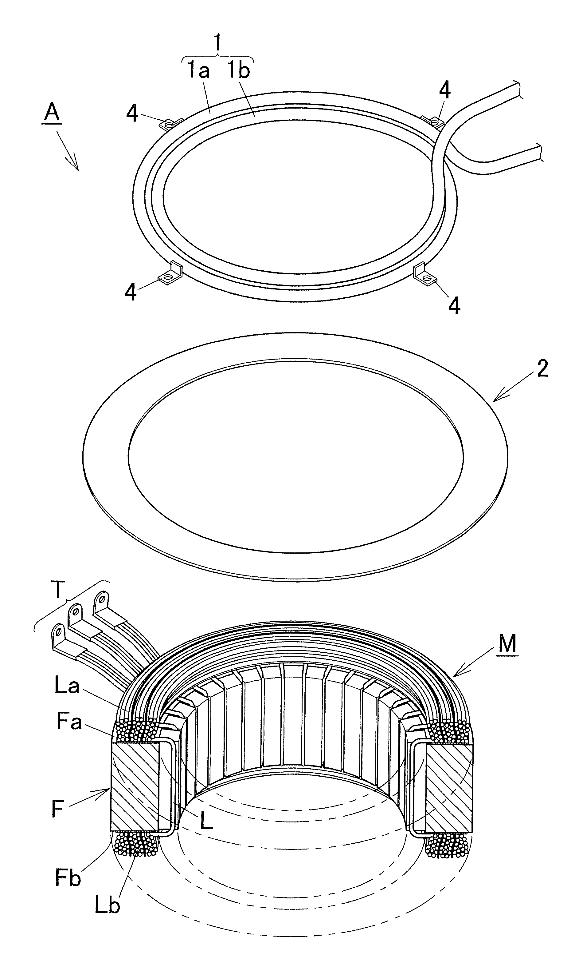
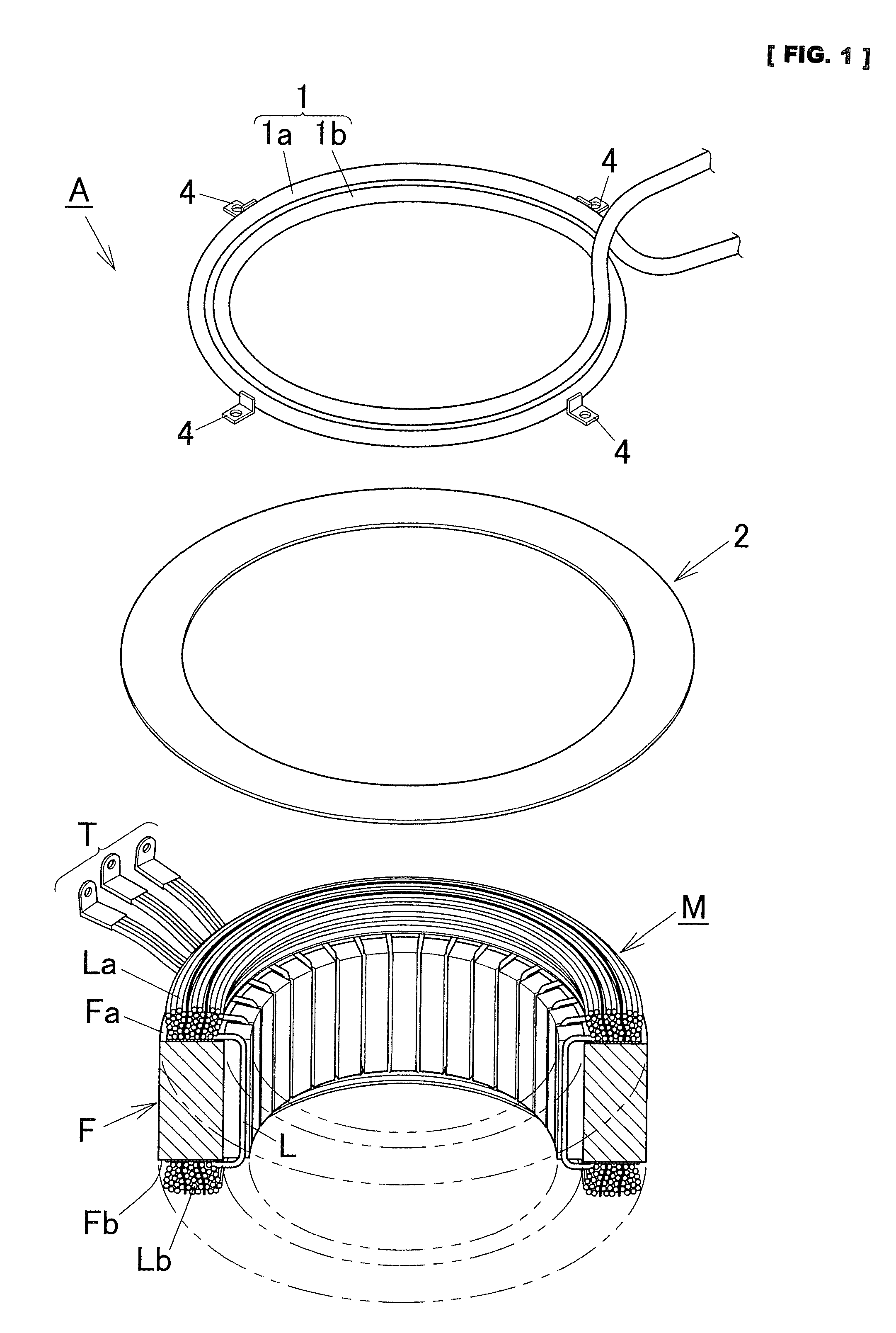
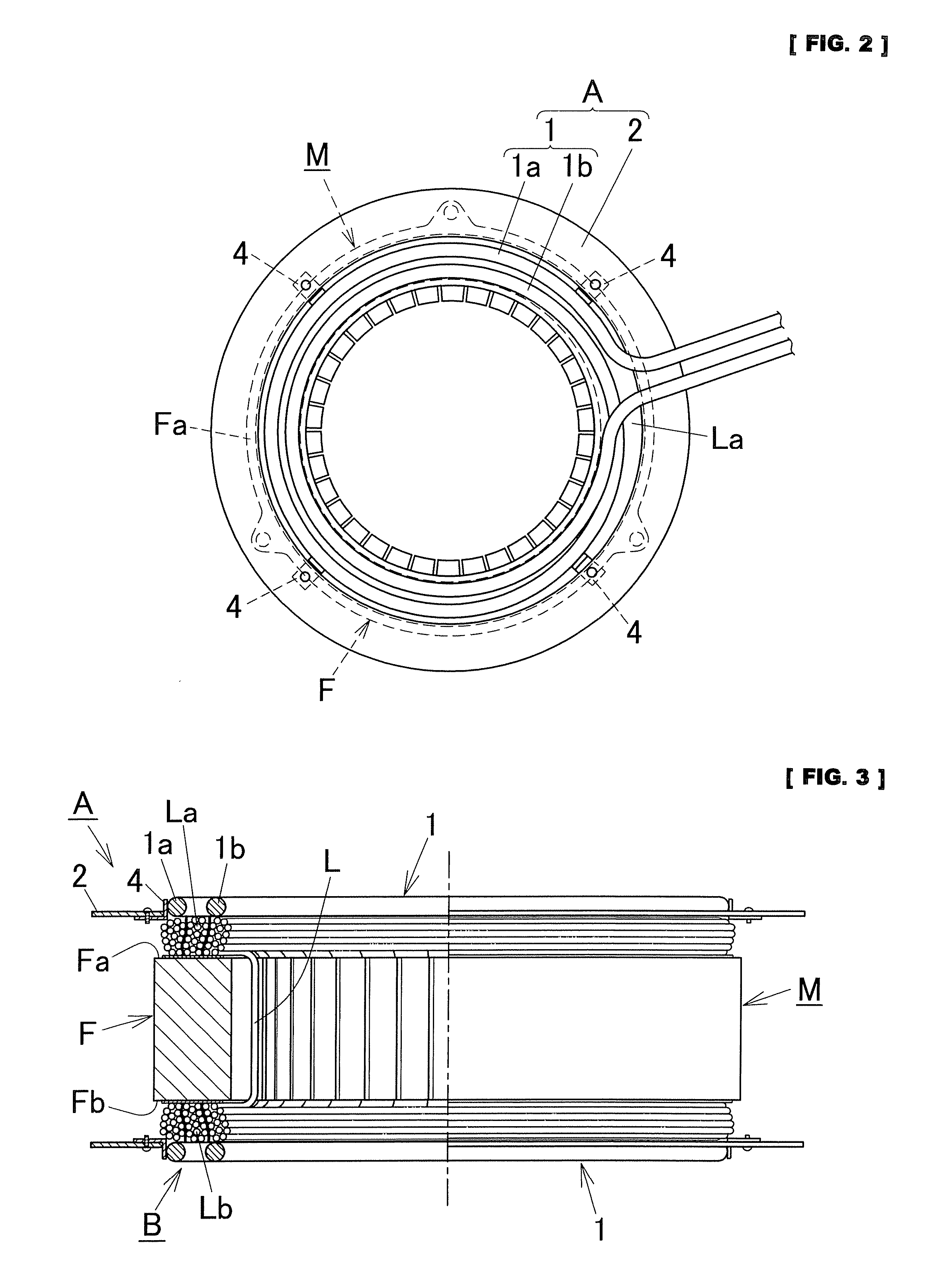
[0109]FIG. 1 is an exploded perspective view showing a stator coil heating apparatus according to an embodiment of the present invention, FIG. 2 is a plain view showing the same stator coil heating apparatus set on a stator, and FIG. 3 is a half cutaway view showing the same stator coil heating apparatus set on a stator.

[0110]This embodiment will be explained with the example of heating a stator coil of a stator that is an automotive electrical generator. However, it is not limited thereto.

[0111]As shown in FIG. 1 through FIG. 3, a stator M comprises a circular core F constructed of a plurality of thin silicon steel plates layered in the thickness direction and a three-phase stator coil L wound around the core F. And circular winding coil bases La and Lb are sticking out of the end faces Fa and Fb of the core F in the thickness direction (the axial direction: the vertical direction in Figure) thereof, respectively. The entire stator coil L including these winding coil bases La and L...


PUM


Abstract

A stator coil heating apparatus and a stator coil heating method that are capable of effectively preventing a core from thermal deformation particularly caused due to a magnetic flux generated by a coil head, without the problem of heating temperature variation, and also shortening a time for the process of heating a stator coil, are provided.
A stator coil heating apparatus A to heat a stator coil L wound around a circular core F, comprises: induction heating coil heads 1 and 11 that heat the circular coil L by generating an inductive effect acting from outside in the thickness direction of the core F, against circular winding coil bases La and Lb that are sticking out of end faces Fa and Fb of the core F in the thickness direction thereof; and shields 2 and 12 that block a magnetic flux generated by the coil heads 1 and 11, out of the end faces Fa and Fb of the core F in the thickness direction thereof.

Description

FIELD OF THE INVENTION[0001]The present invention relates to a stator coil heating apparatus and a stator coil heating method that are used in the manufacturing process of a stator such as an automotive electrical generator.BACKGROUND OF THE ART[0002]As generally practiced, in the manufacturing process of a stator that is an automotive electrical generator, a three-phase stator coil is wound around a circular core, and after that, the entire stator coil including a circular winding coil base that is sticking out of an end face of the core in the axial direction thereof, is impregnated with varnish. In this state of things, the stator coil is heated, and thereby the impregnating varnish is harden-dried.[0003]After impregnating the stator coil with varnish, it is conventionally practiced that the entire stator is inserted into a heating furnace while being rotated, and thereby the impregnating varnish is harden-dried with heated air.[0004]However, in the method of harden-drying varnis...

Claims


Application Information

Patent Timeline
Patent Type & Authority Applications(United States)
IPC IPC(8): H02K57/00
CPCH05B6/36H02K15/12
Inventor MATSUMOTO, KEISHIFUKUMARU, KENICHIROHAYASHI, IKUOMIYAKE, HIDEAKIKIMURA, HIDEAKIKOIDE, SATOSHI
Owner TOYOTA JIDOSHA KK
Why Eureka
Try Eureka