
Housing Fastening Method

a fastening method and housing technology, applied in the direction of machines/engines, mechanical equipment, liquid fuel engines, etc., can solve problems such as deformation of fasteners, and achieve the effect of reducing the fastening for

Inactive Publication Date: 2010-11-25
IHI CORP
View PDF12 Cites 21 Cited by
  • Summary
  • Abstract
  • Description
  • Claims
  • Application Information

AI Technical Summary

Benefits of technology

[0006]The present invention has been made to solve the problems as mentioned above. An object of the present invention is to provide, by contriving a housing structure, a housing fastening method and turbocharger capable of keeping down the reduction in fastening force applied by a fastener such as a G-coupling even when housings are exposed to high temperature.

Problems solved by technology

Further, exposure of the turbine housing inside to high-temperature exhaust gas causes thermal expansion of its flange portion, which in turn causes deformation of the fastener.

Method used


Image

  • Housing Fastening Method
  • Housing Fastening Method
  • Housing Fastening Method

Examples


Embodiment Construction

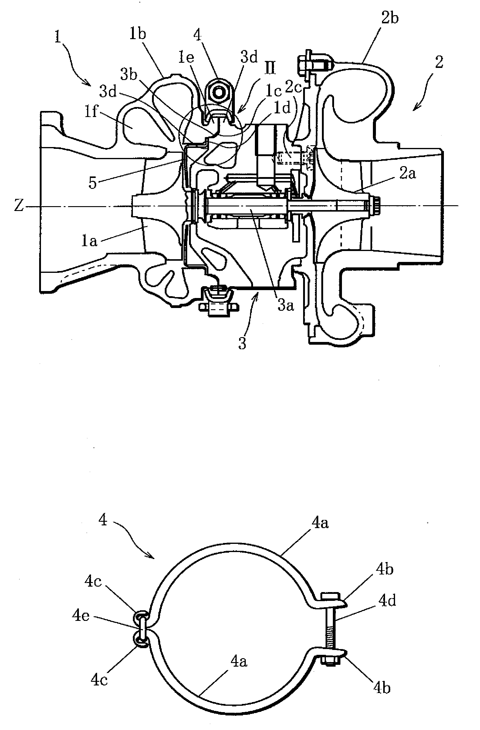
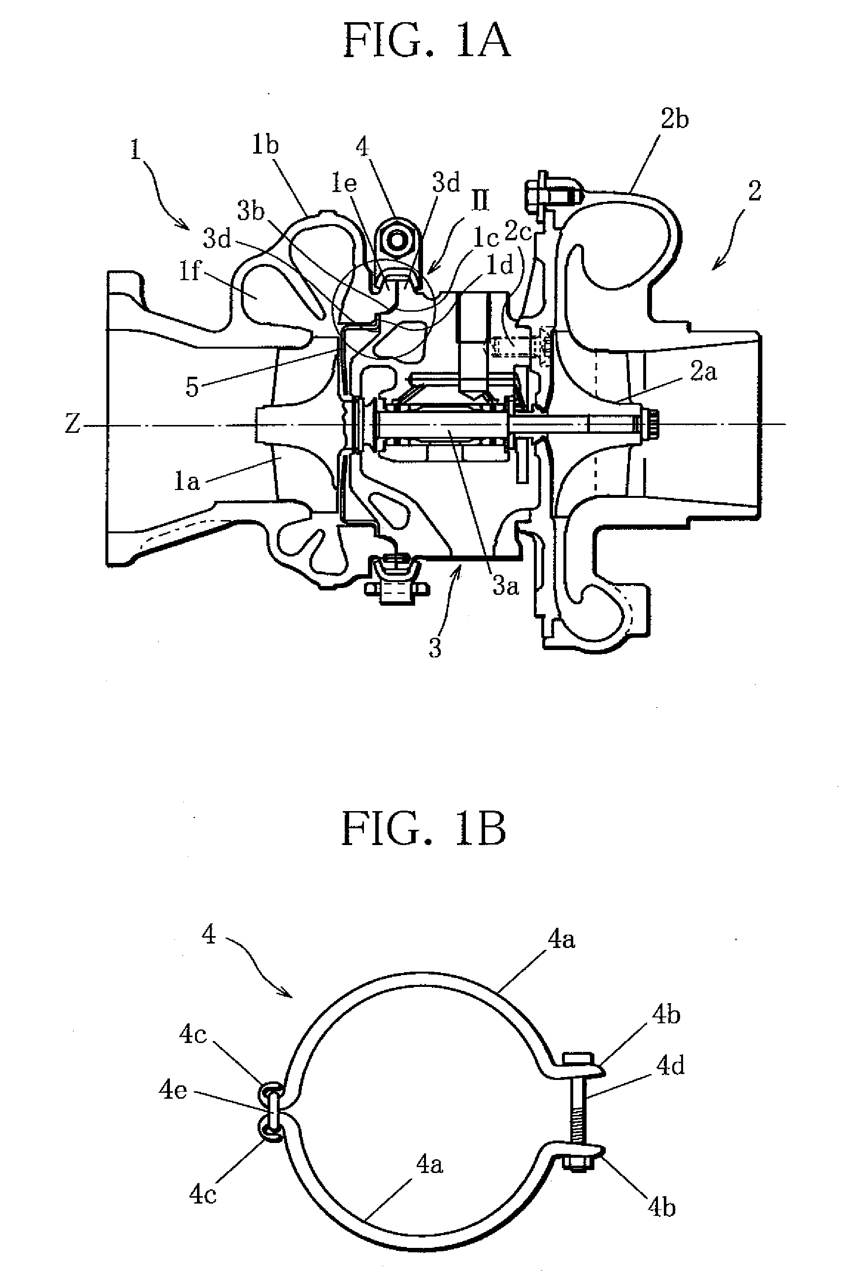
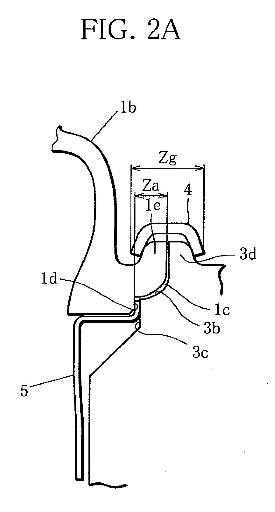
[0031]Referring to FIGS. 1A to 5B, embodiments of the present invention will be described below. FIG. 1A is a longitudinal cross-sectional view of a turbocharger according to the present invention, and FIG. 1B a front view of a G-coupling shown in FIG. 1A. FIG. 2A shows portion II of FIG. 1A on an enlarged scale, and FIG. 2B shows a portion corresponding to the portion shown in FIG. 2A in prior art.

[0032]The turbocharger according to the present invention shown in FIG. 1A comprises a turbine 1 including a bladed rotor la rotated by a fluid supplied thereto, a compressor 2 including an impeller 2a for drawing in air, connected with the bladed rotor 1a by a rotating shaft 3a, a turbine housing 1b constituting an outer shape of the turbine 1, and a bearing housing 3 rotatably supporting the rotating shaft 3a. The turbine housing 1a and the bearing housing 3 and the bearing housing 3 [sic] are assembled as follows: A projecting portion 3b of the bearing housing 3 is inserted in a recess...


PUM


Abstract

An object of the present invention is to provide, by contriving a housing structure, a housing fastening method and turbocharger capable of keeping down a reduction in fastening force applied by a G-coupling even when housings are exposed to high temperature.The present invention provides a turbocharger comprising a turbine 1 including a bladed rotor 1a rotated by a fluid supplied thereto, a compressor 2 including an impeller 2a for drawing in air, connected with the bladed rotor 1a by a rotating shaft 3a, a turbine housing 1b constituting an outer shape of the turbine 1, and a bearing housing 3 rotatably supporting the rotating shaft 3a, a projecting portion 3b of the bearing housing 3 being inserted in a recessed portion 1c of the turbine housing 1b such that an end face 3c of the projecting portion 3b butts against a step portion 1d of the recessed portion 1c serving as a stopper face, a flange portion 1e around the recessed portion 1c and a flange portion 3d around the projecting portion 3b being fastened together by an annular fastener positioned outside, wherein the shapes of the recessed portion 1c and the projecting portion 3b are determined by regulating the axial position of the stopper face of the step portion 1d.

Description

TECHNICAL FIELD[0001]This invention relates to a housing fastening method for fastening housings together by a fastener such as a G-coupling and a turbocharger having housings fastened together by a fastener such as a G-coupling, and particularly a housing fastening method and turbocharger capable of keeping down a reduction in fastening force applied by a fastener.BACKGROUND ART[0002]A rotary machine which obtains power by converting kinetic energy of a fluid supplied to its bladed rotor to rotation of the bladed rotor is generally called a turbine. A type in which a fluid is supplied to the bladed rotor radially and discharged axially is called a radial turbine, in particular. An automotive turbocharger is a device using such radial turbine. The automotive turbocharger comprises a gas turbine including a bladed turbine rotor rotated by exhaust gas supplied thereto and a compressor including an impeller for drawing in air, connected with the bladed turbine rotor coaxially. The air ...

Claims


Application Information

Patent Timeline
Patent Type & Authority Applications(United States)
IPC IPC(8): F04D29/40
CPCF01D25/243F02B37/00F05D2260/20F05D2260/39F05D2220/40F02B39/00F05D2230/642
Inventor SAKAI, YASUTAKA
Owner IHI CORP
Learn More