Backup management method
a management method and backup technology, applied in the field of backup and recovery, can solve the problems of difficult management of it equipment and inability to make efficient use of backup data, and achieve the effect of efficient application of vm backup
- Summary
- Abstract
- Description
- Claims
- Application Information
AI Technical Summary
Benefits of technology
Problems solved by technology
Method used
Image
Examples
embodiment 1
(1-2) Overview of Embodiment 1
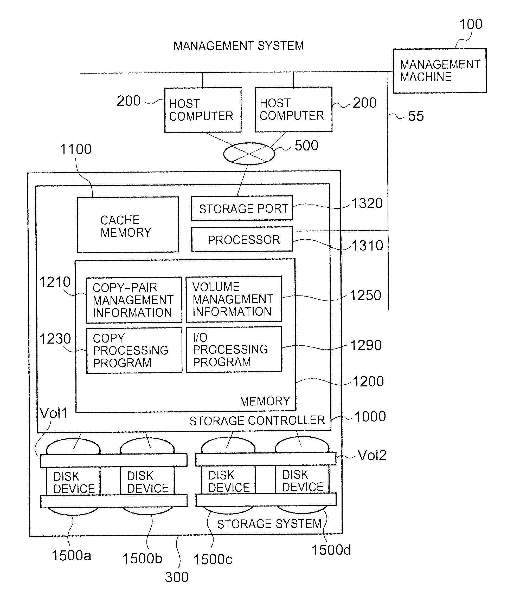
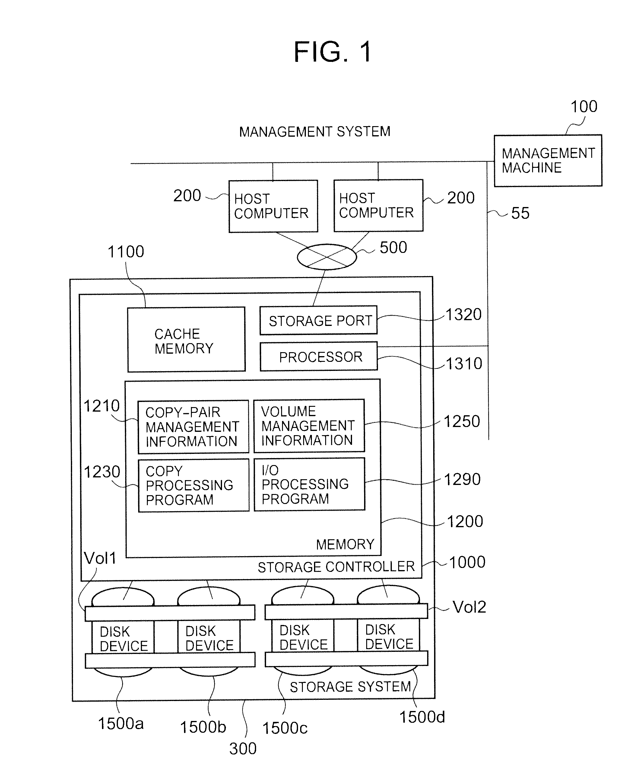
[0093]An overview of the first embodiment will be explained next. In the first embodiment, an explanation was given of an example in which the snapshot function provided by the virtualization program 212 of the host computer 200 and the copy function provided by the storage system are combined in a server virtualization environment to realize a VM backup.
[0094]FIG. 14 is a conceptual diagram for illustrating the concept of the VM backup in the first embodiment.
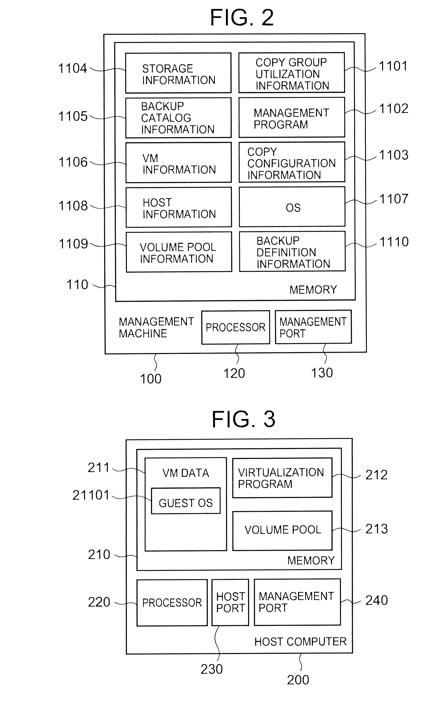
[0095]The virtualization program 212 runs on the host computer 200. By running the virtualization program 212, the host computer is able to provide one or more VM to a client machine or a user that is using this host computer. The host computer 200 writes and reads to and from one or more logical volumes provided by the storage system 300. The host computer 200 provides a portion of the storage area of the accessed logical volume to the VM as a virtual volume, and writes a VM file to the logical v...
embodiment 2
[0238]Next, a second embodiment of the present invention will be explained. According to the second embodiment, it is possible to enhance the capacity efficiency of backup data stored in the storage system. This is able to be realized by making the timing of an arbitrary VM snapshot file acquisition by the host computer 200 asynchronous to the timing at which the storage system 300 implements the copy function for a logical volume.
(2-1) Overview of Second Embodiment
[0239]The enhancement of backup data capacity efficiency will be explained using the schematic VM backup operation diagram of FIG. 27. The backups of three VM (VM1, VM2, VM3) will be considered. In the second embodiment, the computer system first uses the storage system-based logical volume copy function after having acquired a certain portion of the snapshot files of VM1, VM2 and VM3. Subsequent to using the copy function, this computer system deletes all the snapshot files. In accordance with the above-mentioned steps, ...
second embodiment
(2-3) Operation of Second Embodiment
[0241]Next, the operation of the second embodiment will be explained in terms of the differences with the operation of the first embodiment. Specifically, there are changes to the schedule definition and backup operations, and a storage system-based copy processing operation is added.
(2-3-1) Schedule Definition Operation
[0242]First, in the schedule definition operation (FIG. 19) in accordance with the management computer 100, the processing content of the step (Step 5210)for inputting the interval for implementing the storage system copy function, and of the step (Step 5260) for registering a backup task in the scheduler differ.
[0243]In Step 5210, a “restore point objective” input area is added at the bottom of the input screen of FIG. 20 as in the backup schedule input screen of FIG. 28. A value obtained via this input area is stored in the RPO information 1111. In Step 5260, the management computer 100 registers processing for two operations in ...
PUM
 Abstract
Description
Claims
Application Information
 - R&D
- Intellectual Property
- Life Sciences
- Materials
- Tech Scout
- Unparalleled Data Quality
- Higher Quality Content
- 60% Fewer Hallucinations
Browse by: Latest US Patents, China's latest patents, Technical Efficacy Thesaurus, Application Domain, Technology Topic, Popular Technical Reports.
© 2025 PatSnap. All rights reserved.Legal|Privacy policy|Modern Slavery Act Transparency Statement|Sitemap|About US| Contact US: help@patsnap.com


