

Spark plug having a reduced physical volume
a technology of physical volume and spark plug, which is applied in the direction of spark plugs, machines/engines, mechanical equipment, etc., can solve the problems of decreasing the physical volume of spark plugs and the physical volume provided for each cylinder, and achieve the effect of reducing the physical volume required for tools
- Summary
- Abstract
- Description
- Claims
- Application Information
AI Technical Summary
Benefits of technology
Problems solved by technology
Method used
Image

Examples
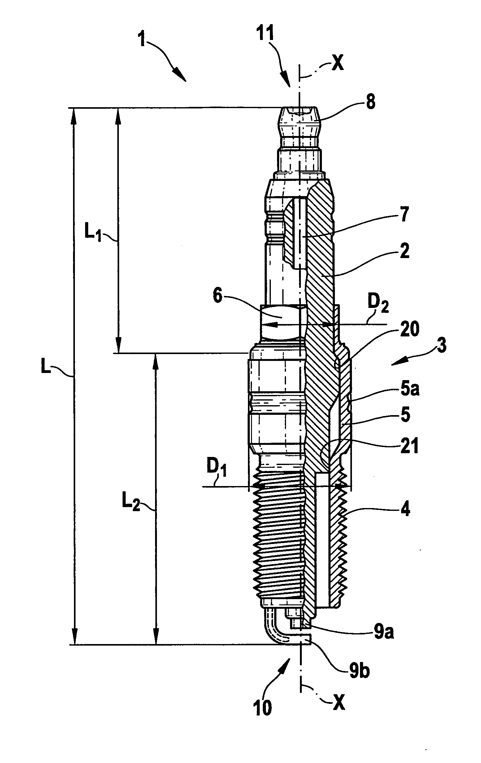
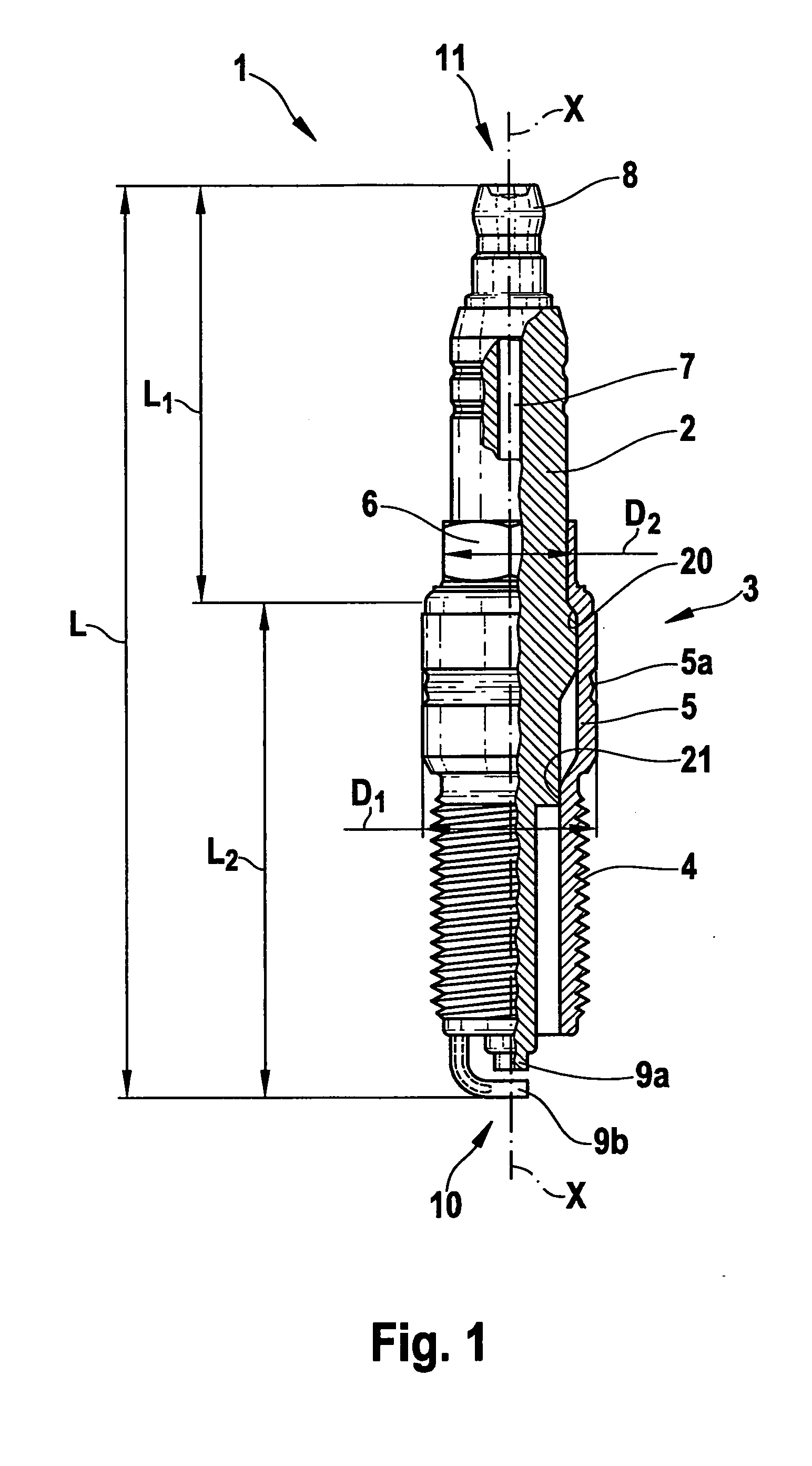
first exemplary embodiment
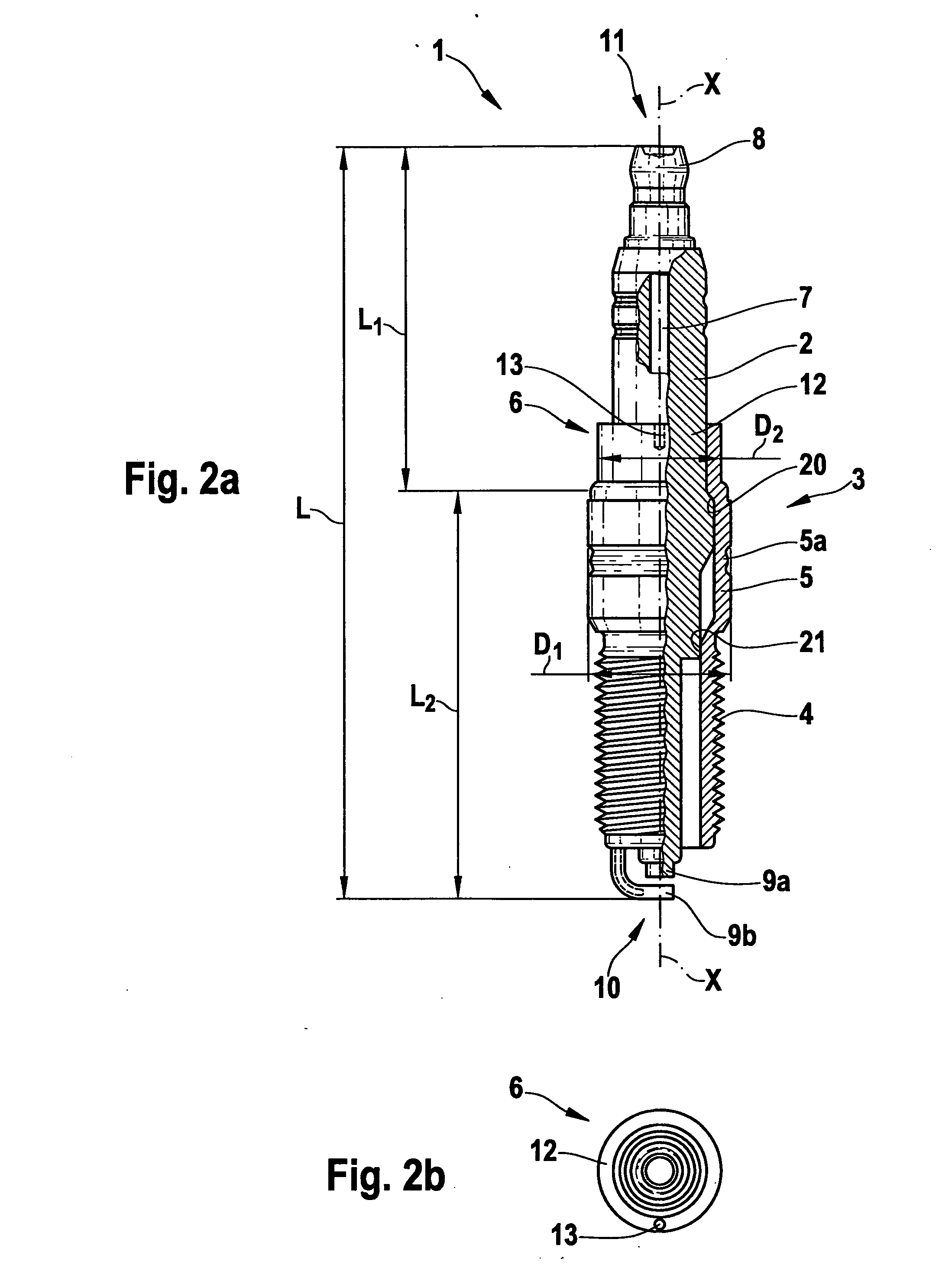
[0026]In contrast to the first exemplary embodiment, spark plug 1 in the second exemplary embodiment has a tool engagement area 6 of an alternative design. As shown in FIGS. 2a and 2b, tool engagement area 6 is formed by a sleeve-like area 12 which forms a single unit with housing 3. Sleeve-like area 12 is again situated downstream from first sealing area 20 in the direction of end 11 on the combustion-chamber side. A bore 13, which is used to accommodate a correspondingly designed fitting tool (not illustrated), is provided in ring-shaped, sleeve-like area 12. When the fitting tool is attached to ring-shaped, sleeve-like area 12, a torque is thereby transmittable to spark plug 1 via an element of the tool projecting into bore 13 and via bore 13. This makes it possible to easily fit and remove the spark plug. Ring-shaped sleeve area 12 may be provided in a particularly simple and cost-effective manner. The outer diameter of the tool is preferably smaller than the maximum outer diame...
third exemplary embodiment
[0028]The third exemplary embodiment generally corresponds to the second exemplary embodiment, a radial groove 14 being provided in the third exemplary embodiment on a ring-shaped sleeve area 12, which forms a single unit with housing 3. Like bore 13 in the second exemplary embodiment, radial groove 14 in the third exemplary embodiment is used to transmit, to spark plug 1, a torque which is applied to a tool having a matching design (not shown). In other respects, this exemplary embodiment corresponds to the preceding exemplary embodiments, so that reference may be made to the description provided therefor.
[0029]A spark plug according to a fourth exemplary embodiment of the present invention is described below with reference to FIG. 4. Equivalent or functionally equivalent parts are again identified by the same reference numerals as in the preceding exemplary embodiments.
[0030]The spark plug in the fourth exemplary embodiment has a tool engagement area 6 which is situated directly o...
PUM
 Abstract
Description
Claims
Application Information