Device for Controlling the Rate of Flow of a Fluid

a technology of fluid flow and control device, which is applied in the direction of flow monitors, intravenous devices, other medical devices, etc., can solve the problems of loss of a wide range of physical and mental faculties, increased challenge, and abnormal pressure in the brain

Inactive Publication Date: 2010-12-02
CENTRAX
View PDF14 Cites 4 Cited by
  • Summary
  • Abstract
  • Description
  • Claims
  • Application Information

AI Technical Summary

Benefits of technology

[0020]The selection means may further comprise a magnetic marker, which may be provided in the selection means, such that the orientation of the selection means may be determined through use of a compass or magnetic indicator held proximate the device...

Problems solved by technology

Hydrocephalus may be congenital, accidental or age related and can result in loss of a wide range of physical and mental faculties.
The primary technical challenge associated with this method of treatment is developing the capacity to control the conditions of pressure and flow within the brain in such a manner as to enable lost faculties to be restored, depending on the severity of the condition.
This challenge is exacerbated by the greatly differing range of impairment between different patients.
If the flow imbalance referred to above is not addressed, pressure within the brain rises to an abnormal level.
Such increased pressure causes th...

Method used


Image

  • Device for Controlling the Rate of Flow of a Fluid
  • Device for Controlling the Rate of Flow of a Fluid
  • Device for Controlling the Rate of Flow of a Fluid

Examples


Embodiment Construction

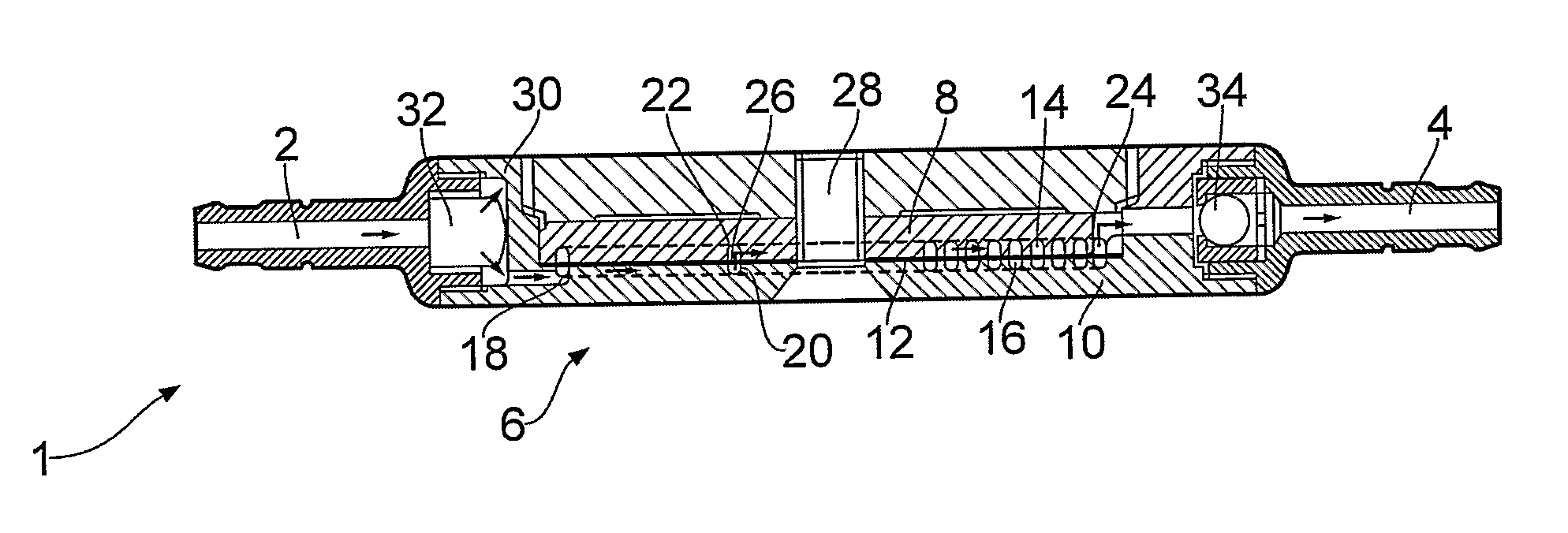
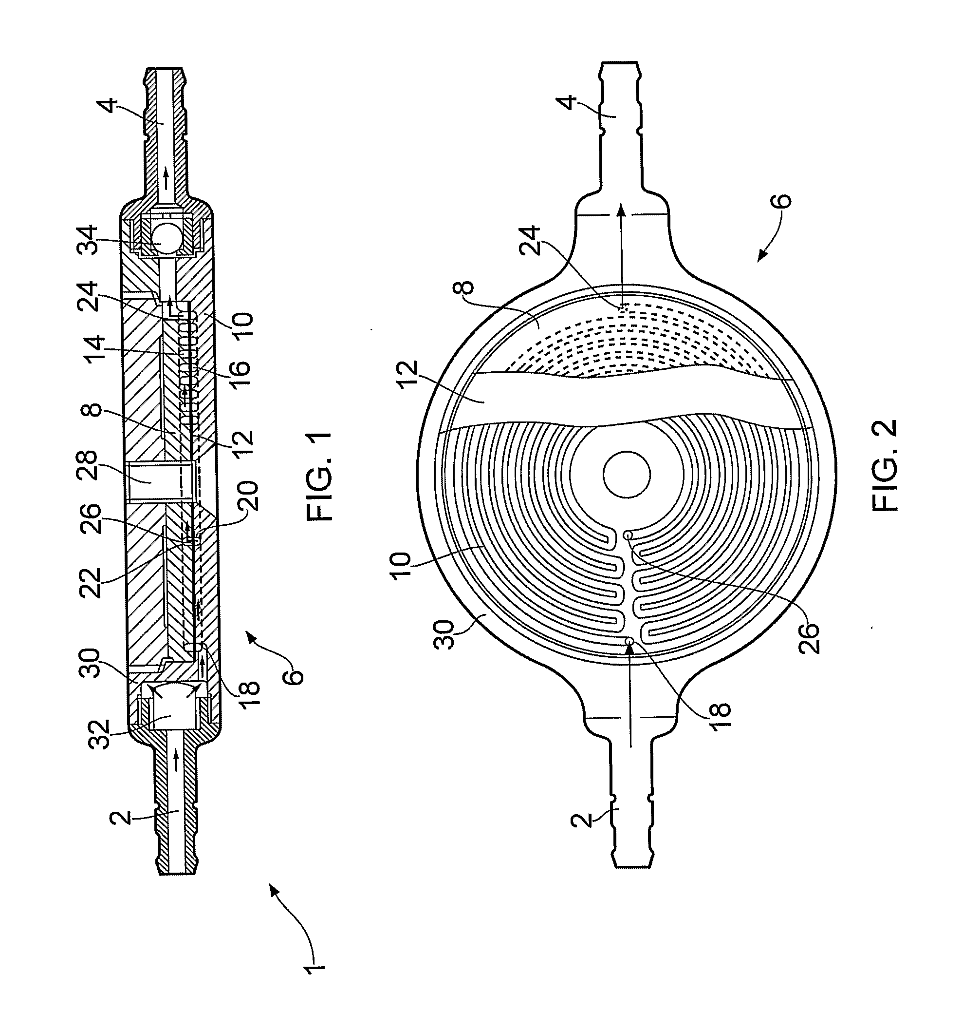
[0046]With reference to FIGS. 1 and 2, a device 1 for diverting fluid from the ventricles of the brain comprises an inlet 2, an outlet 4 and a resistance member 6 operatively coupled between the inlet 2 and the outlet 4. The resistance member 6 comprises an upper member 8, a lower member 10 and a substantially circular plate 12 sandwiched between the upper and lower members 8, 10. The upper and lower members 8, 10 each have a substantially circular, planar surface in contact with the plate 12. The planar surfaces of the upper and lower members 8, 10 each comprise a groove or channel, which forms a continuous closed resistance tube 14, 16 when the grooved surface is in abutment with the plate 12. The lower resistance tube 16 formed by the lower member 10 follows a convoluted flow path from a fluid entry point 18, at a radially outer position on the planar surface of the lower member 10, to a fluid exit point 20, at a radially inner position on the planar surface of the lower member 1...


PUM


Abstract

A device (1) for controlling the rate of flow of a fluid such as fluid which is diverted from a part of a human or animal body. The device comprises: an inlet (2); an outlet (4); and a resistance member (6), operatively connected to the inlet (2) and the outlet (4), the resistance member (6) comprising: a first plate (8), a surface of which comprises a groove which defines a resistance flow channel, an entry of the flow channel being in fluid communication with the inlet (2) and an exit of the flow channel being in fluid communication with the outlet (4); and a second plate (12), the second plate being held in abutment with the grooved surface of the first plate (8) so as to define a resistance (tube 14).

Description

[0001]The present invention relates to a device for controlling the rate of flow of a fluid and may for example, be used to divert fluid from the ventricles of the brain to another part of the body.BACKGROUND[0002]Hydrocephalus is a defective condition of the brain caused by an imbalance between production of cerebral spinal fluid (CSF) within the brain and the capacity of the brain to re-absorb such fluid at normal pressure. Hydrocephalus may be congenital, accidental or age related and can result in loss of a wide range of physical and mental faculties. The accepted method of treatment of the condition is to divert excess fluid which the brain, through its impairment, is unable to absorb, to some other part of the body such as the right atrium or the peritoneal cavity, where the fluid can re-enter the blood stream. The primary technical challenge associated with this method of treatment is developing the capacity to control the conditions of pressure and flow within the brain in s...

Claims


Application Information

Patent Timeline
IPC IPC(8): A61M27/00
CPCA61M5/16881A61M27/006A61M2205/3515A61M2205/6054A61M2205/8287
Inventor BARR, RICHARD HENRY HOWARD
Owner CENTRAX
Why Eureka
Try Eureka