
Meniscal repair systems and methods

a meniscus and tear technology, applied in the field of meniscus tear surgery, can solve the problems of increasing surgical time and complexity, increasing the onset of osteoarthritis and other complications, and abrasion of the femoral condyle articular cartilage, so as to reduce friction between and reduce the associated friction

Active Publication Date: 2010-12-02
CAYENNE MEDICAL INC
View PDF42 Cites 47 Cited by
  • Summary
  • Abstract
  • Description
  • Claims
  • Application Information

AI Technical Summary

Benefits of technology

[0027]The suture needle comprises a second surface thereof which is substantially flat and on an opposing side of the suture needle relative to the first surface. An advantage of the present invention is that, because of this construction, the interfering contact between the first suture needle surface and the edge of the transfer needle window causes the flat second suture needle surface against the transfer needle bearing surface.
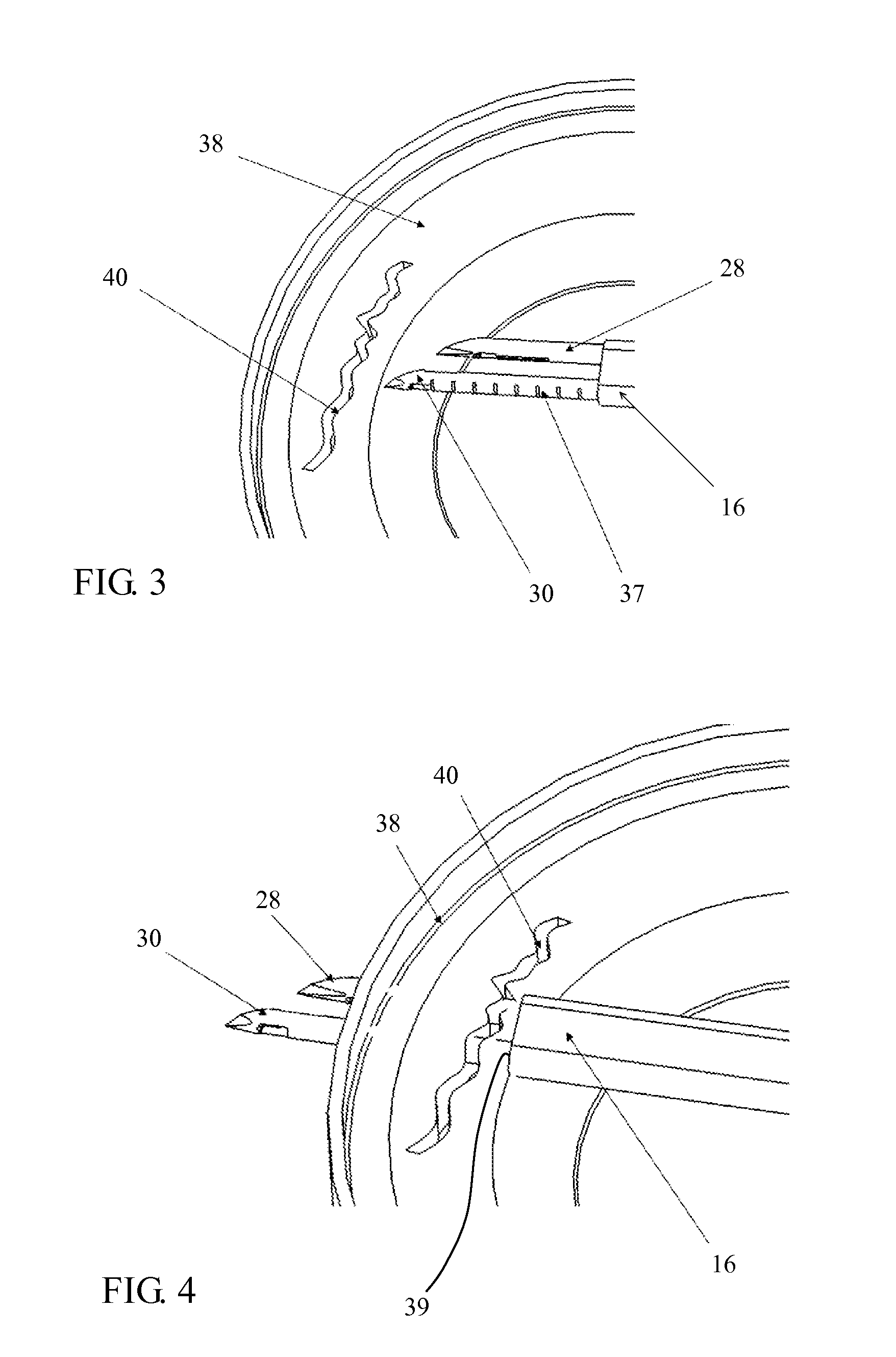
[0028]A suture catch window is provided in the catch needle for receiving the suture needle into the catch needle. The suture needle comprises angled surfaces extending from a distal tip thereof, and the suture catch window also comprises angled surfaces. The suture needle angled surfaces and the suture catch window angled surfaces are configured to correspond to one another so that the suture needle slides and ramps along the suture catch window angled surfaces to assist in guiding the suture needle into and out of the suture catch window.
[0029]An extendable catch plunger is disposed in the catch needle for capturing suture therein when it is transferred from the transfer needle, wherein the catch plunger comprises an angled distal surface which is configured to mate with a corresponding one of the angled suture needle surfaces. Preferably, a second window is disposed on the catch needle on a side opposed to the side on which the first window is disposed, through which a distal end of the suture needle extends when the suture needle is fully extended into the catch needle.
[0030]The inventive device also comprises a retractable insertion sheath for covering the transfer needle and the catch needle when the device is inserted into a procedural site. The proximal actuator portion comprises an insertion sheath actuator for retracting and advancing the insertion sheath. A depth limiting apparatus is provided for limiting the depth of insertion of the needles into the procedural site, which is integrated with the insertion sheath actuator. The depth limiting apparatus comprises a depth gauge disposed on the proximal actuator portion. The insertion sheath actuator comprises a button which slides axially along a slot in said proximal actuator portion, with the depth gauge comprising graduated numbered markings disposed along the slot, so that a practitioner can retract the sheath by sliding the insertion sheath actuator button to a selected position along the slot to control the depth of insertion of the device, between a locked forward configuration and a locked backward configuration.
[0031]Another innovative feature of the present invention is a cleat disposed within the proximal actuator portion, which is attached to a length of suture extending from the proximal actuator portion and having a pre-tied knot thereon. The cleat is configured to selectively apply tension to the suture. Prior to deployment, the pre-tied knot is disposed beneath the sheath and there is a substantial length of slack suture within the proximal actuator portion. The pre-tied knot is deployed to secure the tissue repair by pulling the device proximally away from the procedural site, so that the pre-tied knot slides distally over the needles and length of suture, with the slack suture attached to the cleat simultaneously being reduced.
[0032]In a preferred embodiment, the suture needle is comprised of nitinol, and the transfer needle is comprised of stainless steel, though other suitable biocompatible materials may, of course, be used. Preferably, to reduce friction associated with moving the suture needle back and forth between the transfer needle and the catch needle, an oxide layer infused with tungsten disulfide is formed between the suture needle and the transfer needle.

Problems solved by technology

However, over time, it has become known in the field that removing substantial portions of the meniscus often accelerates the onset of osteoarthritis and other complications which develop when the shock absorbing meniscuses in the knee are absent.
These techniques involve several access ports into the surgical site, and several instrument exchanges during the procedure, increasing surgical time and complexity.
This is a much easier method to execute than the suture-only method discussed above, but its downside is that it leaves a plastic head in the articular space, which causes abrasion to the femoral condyle articular cartilage.
The downside risk that still exists with this approach is that of a hard plastic loose body remaining at the procedural site.
Should some sort of failure occur, the hard plastic implant may come loose and cause damage in the articular space.

Method used


Image

  • Meniscal repair systems and methods
  • Meniscal repair systems and methods
  • Meniscal repair systems and methods

Examples


Embodiment Construction

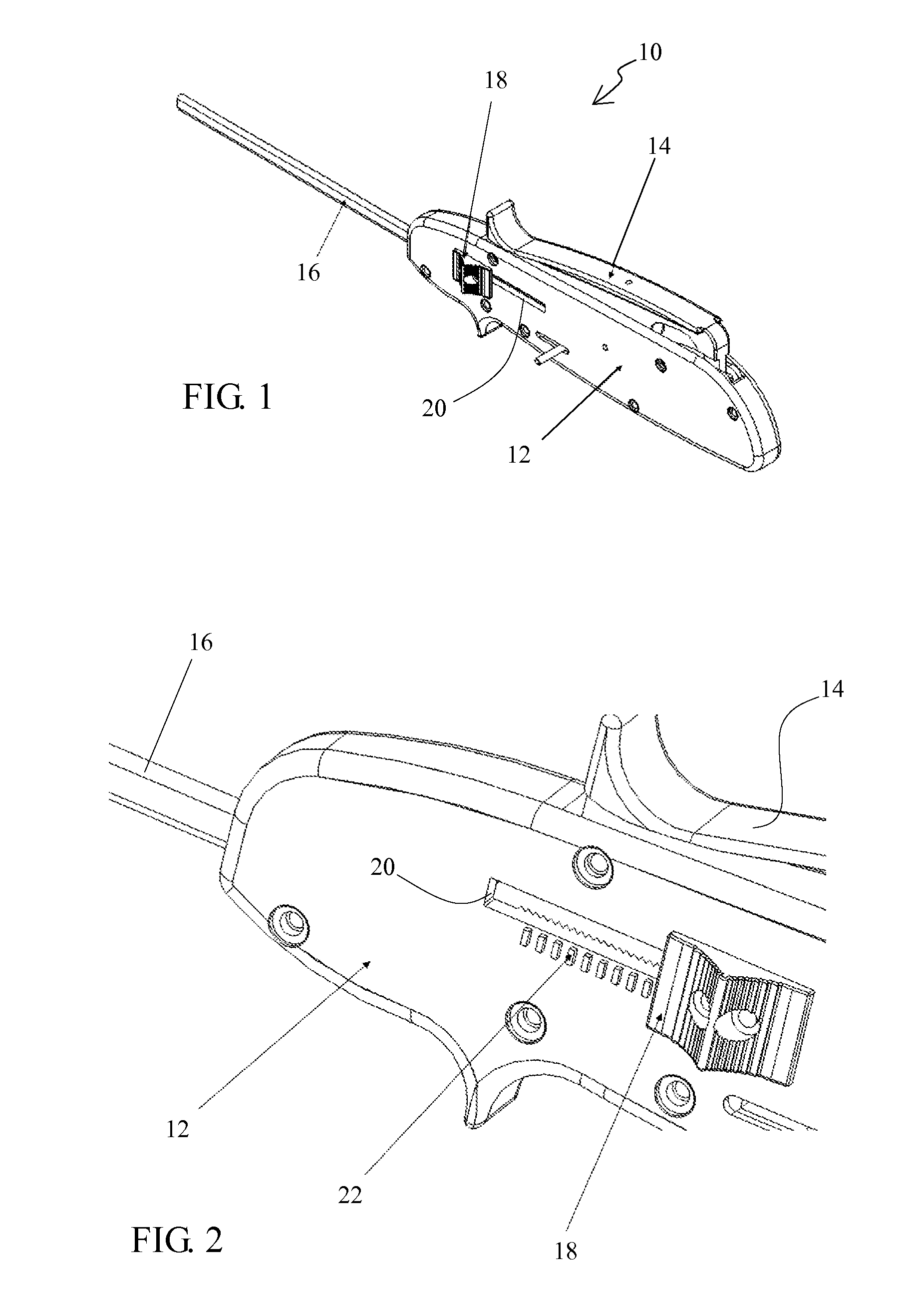
[0072]Referring now more particularly to the drawings, there is shown in FIG. 1 an embodiment of a meniscal repair device 10 constructed in accordance with the principles of the present invention. The device 10 comprises a handle 12 which has a suture needle advancement lever 14. Distally of the handle 12 is provided a depth limiter / insertion sheath 16. A depth limiter / insertion sheath actuation button 18 is disposed on the handle 12.

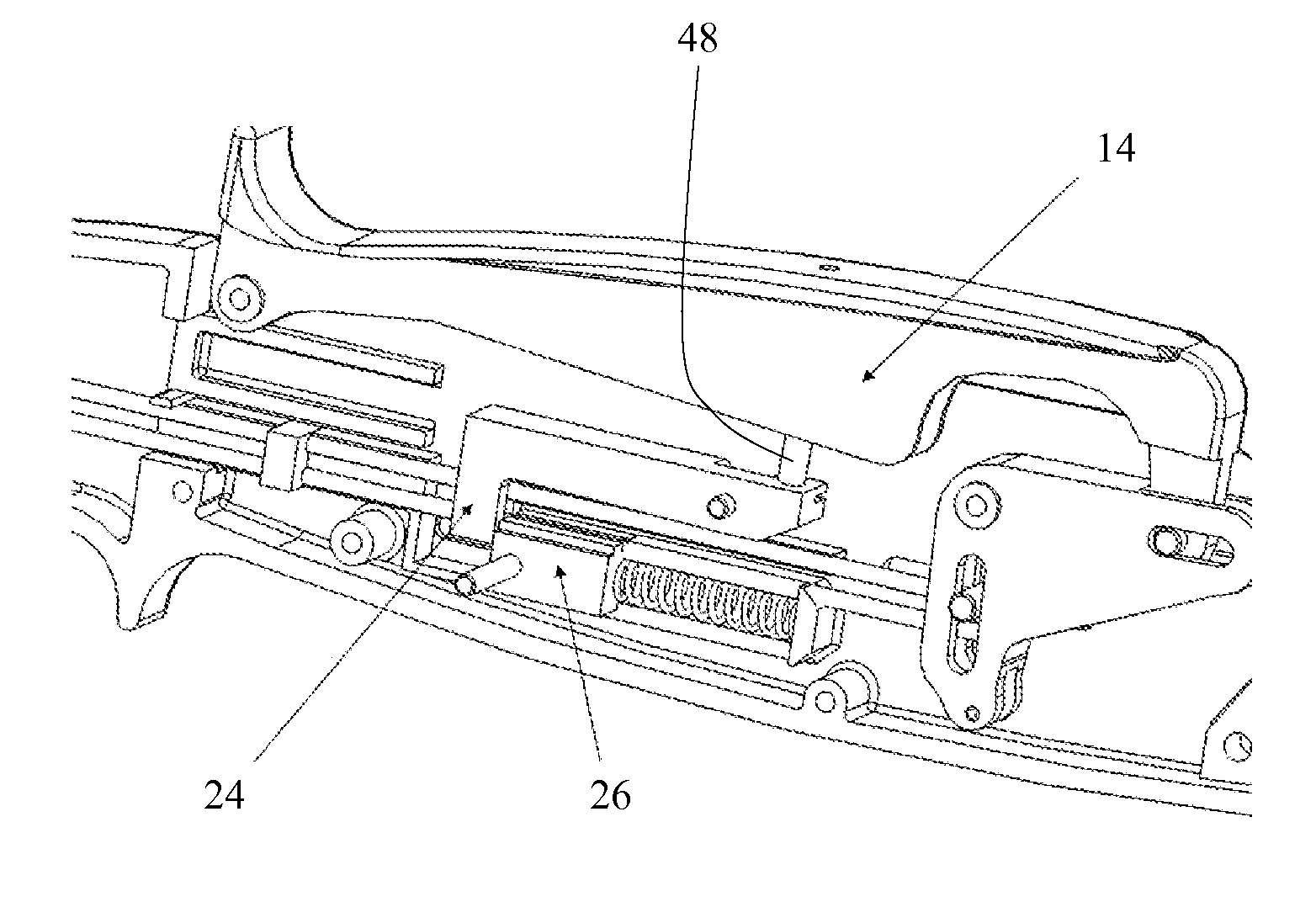
[0073]Now with reference to FIGS. 2 and 7, in addition to FIG. 1, additional constructional details of the handle 12 are illustrated. As shown particularly in FIG. 2, the depth limiter / insertion sheath actuation button 18 travels axially within a slot 20. A depth gauge 22 is provided for purposes which will be described below. In FIG. 7, wherein the cover of the handle has been removed to reveal the internal construction of the handle 12, it can be seen that a piston retention lever 24 and a catch spring piston 26 are disposed therein.

[0074]In FIGS. 6 a...


PUM


Abstract

A device for repairing a tear in a portion of tissue comprises a proximal actuator portion, a transfer needle extending distally from the proximal actuator portion and a catch needle extending distally from the proximal actuator portion. A suture needle is disposed in the transfer needle, and is extendable from the transfer needle toward the catch needle and retractable from the catch needle toward the transfer needle. An extendable catch plunger is disposed in the catch needle for capturing suture therein when it is transferred from the transfer needle. A retractable insertion sheath is provided for covering the transfer needle and the catch needle when the device is inserted into a procedural site. A depth limiting apparatus limits the depth of insertion of the needle into the procedural site.

Description

[0001]This application claims the benefit under 35 U.S.C. 119(e) of the filing date of Provisional U.S. Application Ser. No. 61 / 174,953, entitled Arthroscopic Meniscal Repair System and Methods, filed on May 1, 2009. This prior provisional application is expressly incorporated herein by reference, in its entirety.[0002]The present application is also related to prior commonly assigned pending U.S. application Ser. No. 12 / 398,100, filed on Mar. 4, 2009, and entitled Arthroscopic Meniscal Repair System and Methods, as well as to prior commonly assigned pending U.S. application Ser. No. 12 / 603,232, filed on Oct. 21, 2009, and entitled Meniscal Repair Systems and Methods. These prior related applications are also herein expressly incorporated by reference, in their entirety.BACKGROUND OF THE INVENTION[0003]The present invention relates to surgical repair of meniscal tears, and more particularly to a unique arthroscopic handheld device and methods for repairing meniscal tears by passing ...

Claims


Application Information

Patent Timeline
Patent Type & Authority Applications(United States)
IPC IPC(8): A61B17/062A61B17/06
CPCA61B17/0469A61B2017/00367A61B2017/00845A61B2017/0472A61B2017/0477A61B2017/0496A61B2017/06042A61B2017/06052A61B2017/06095A61B2017/061A61B2090/064A61B2090/036A61B2090/062A61B2090/0811A61B17/0491A61B17/0482
Inventor BAIRD, KEVIN N.DOMINGO, NICANOR A.
Owner CAYENNE MEDICAL INC
Learn More