
Electronic wear state determination in a valve arrangement

a valve arrangement and electronic technology, applied in the direction of valve operating means/release devices, instruments, mechanical means, etc., can solve the problems of multi-way valves being particularly susceptible to failure, affecting the operation of the entire installation or vehicle, and affecting the operation of the valv

Inactive Publication Date: 2010-12-02
ABB TECH AG
View PDF1 Cites 10 Cited by
  • Summary
  • Abstract
  • Description
  • Claims
  • Application Information

AI Technical Summary

Benefits of technology

[0024]An advantage of the solution according to exemplary embodiments of the present disclosure is, for example, that the use of a pressure sensor within the valve can be entirely dispensed with for the purpose of determining the wear state. The exemplary method according to the present disclosure also provides the preconditions for, in addition to changes in the friction values in the valve mechanism, changes in respect of the spring constant and the parameters of the I / P converter to be determined separately and to be supplied to a diagnosis system. Furthermore, the solution according to the exemplary method of the present disclosure is suitable, for example, for monostable valves in which the valve element is operated from one side by pilot control, whereas the starting position is assumed by a resetting spring. In contrast, for bistable valves with pilot control at both sides, it is more difficult to draw conclusions about the wear state by means of the creation of change profiles of the speed of the switching element since ventilation and venting of the two control chambers which are situated opposite the switching element takes place at the same time.
[0025]Often, only the pressure in one of the control chambers changes as function of the I / P converter and the other control chamber remains at a constant pressure. However, if the behavior of the I / P converter is known, the solution according to the disclosure can by all means be used for bistable valves.
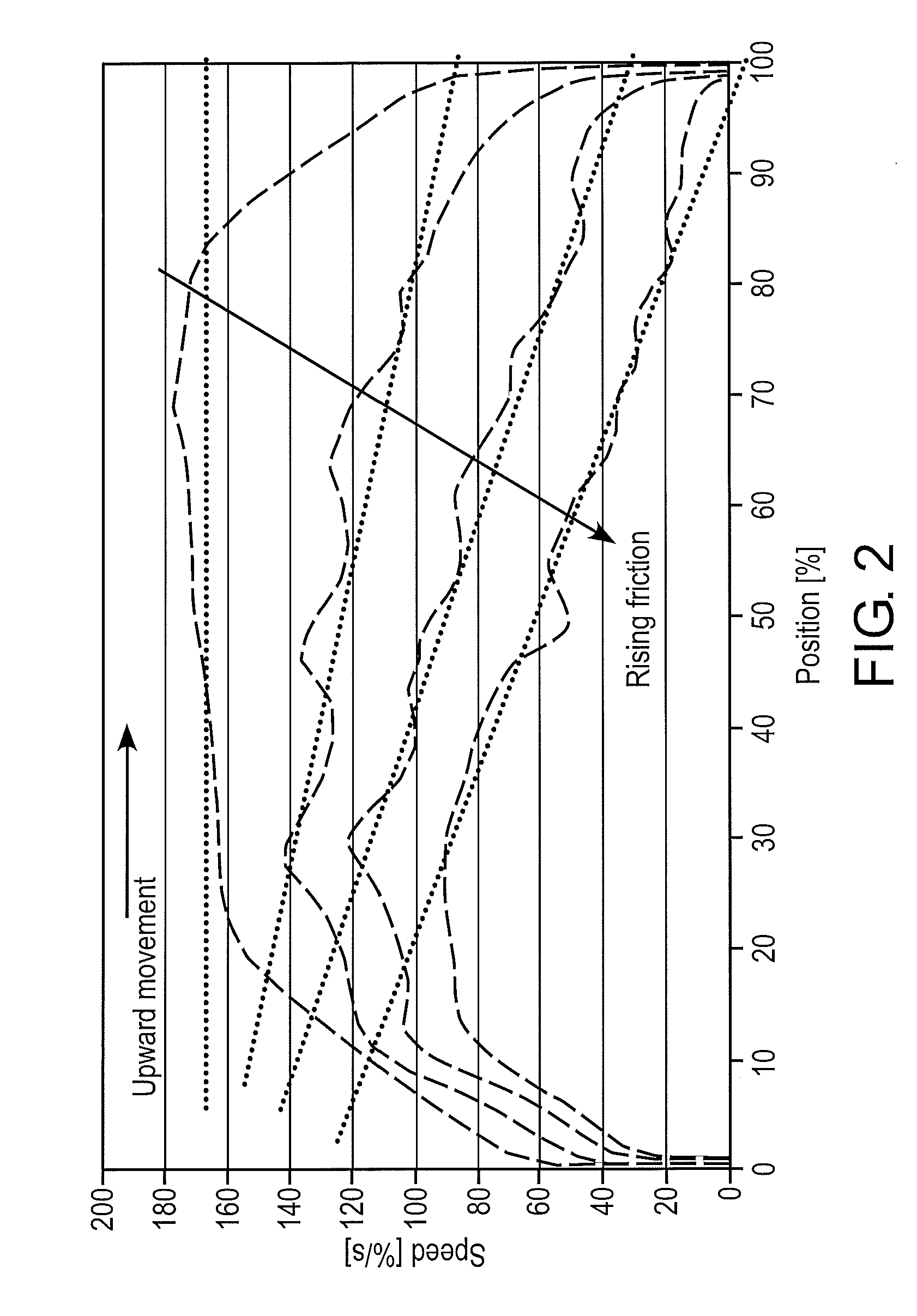
[0026]An exemplary and advantageous measure of the present disclosure provides that a plurality of positions, both along the ventilation distance and along the venting distance, are included in the evaluation in order to determine the speeds prevailing there. Based on the different pressure situations at the I / P converter, the behavior of the compressed air flow to and from actuators connected to the valve, and therefore the movement speed of the valve element, is different during the ventilating and venting stroke. When a monostable valve is vented, a relationship is produced between the venting flow rate and the reduced force of the resetting spring such that the speed depends solely on the actual opening of the UP converter, and therefore the speed is constant. During ventilating, however, the flow rate is constant and the speed of the switching element reduces as the switching stroke rises. The exact link between the reduction in speed and the position is determined by the relationship between the spring force of the resetting spring and the friction. By a plurality of speed determination operations of the switching element during the ventilating stroke and subsequent determination of the change profile, a change in the spring force and other parameters of the pneumatic system can be determined. If, in addition, the speed of the switching element is determined during the venting stroke, a more exact analysis values for the pneumatic system can be obtained.
[0027]A further exemplary and advantageous measure of the present disclosure proposes storing the change profile of the speed profile over the switching stroke, together with the date of the measurement, in a memory element. Corresponding data records form a database which the evaluation unit can in turn access in order to create a wear state forecast from the history of stored change profiles by comparison. In the simplest case, this can be done by extrapolation. If a first determination of the change profile is created and stored when the valve is activated, a change in the friction behavior can already be identified with an actual change profile which is determined at a different time from this for the purpose of wear state identification.
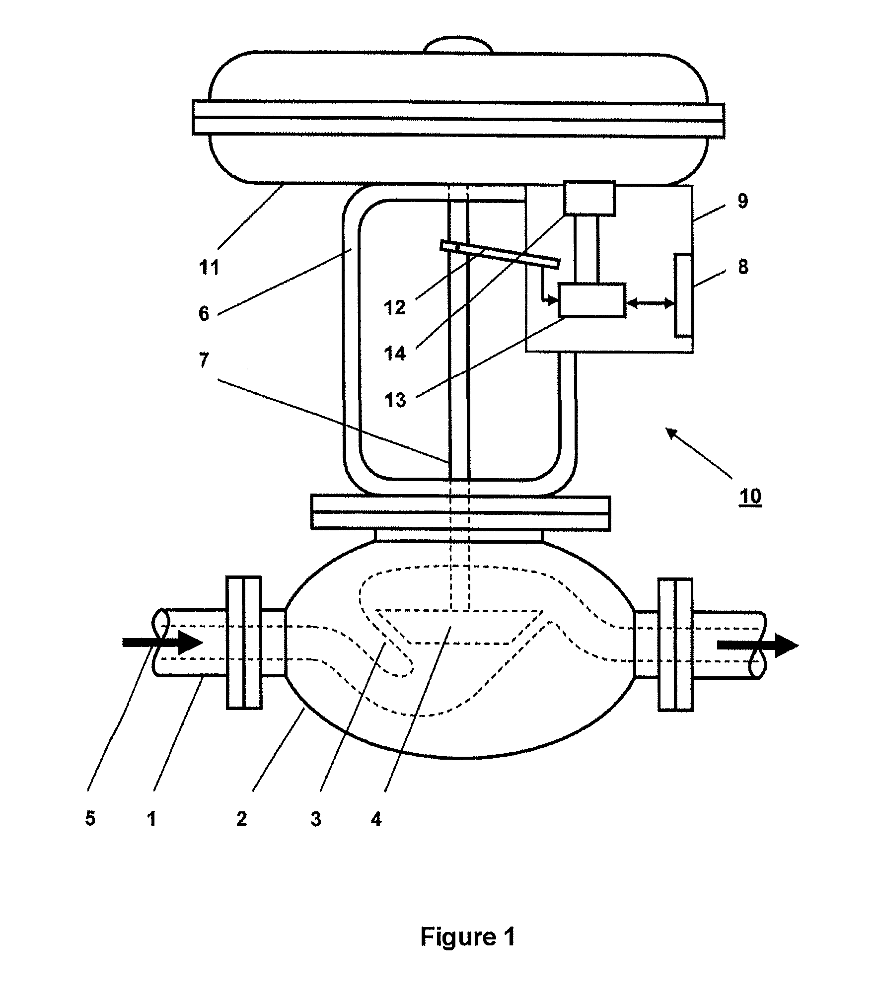
[0029]An exemplary method according to the present disclosure for determining the wear state of the valve mechanism of a monostable pneumatic valve, which can be switched by means of an UP converter, can be implemented by the integration of a position sensor system for determining the time at which various positions of the switching element along the ventilating or venting distance are reached. A downstream evaluation unit evaluates the measured switching times measured as a result by mathematically calculating the speed of the valve element prevailing at the various positions from said switching times. A stored data record including the respective value pair positions with the associated speed, which data record represents the speed profile of the valve mechanism, is created from this. The comparison of two speed profiles, which have been created at different times from one another after many valve switching cycles, can be used to determine a change profile by calculating the difference, where the change profile is used as a measure of the wear state of the valve mechanism. If the change profile shows a significant reduction in the speeds at a plurality of positions of the switching stroke, this indicates, for example, progressive wear of the valve mechanism. It goes without saying that the other parameters which influence the measurement have to be constant.
[0030]The position sensor system which is provided for the purpose of determining the switching points can be formed from a plurality of integrated binary proximity switches which are spaced apart from one another in the valve housing. If an inductive measurement principle is used for this purpose, each of the proximity switches interacts with a permanent magnet which is integrated in the valve element, and the proximity switch, which is inductive in this respect, outputs a binary signal when the maximum value of the voltage which is induced by the movement of the valve element is reached. As an alternative to this, it is also feasible to form the position sensor system as an analog travel measurement sensor which is integrated in the valve housing along the switching distance. A travel measurement sensor of this kind can, for example, be in the form a kind of slide resistor with which any desired position of the valve element along the switching distance can be established. However, a travel measurement sensor which operates in a contact-free manner should preferably be used in order to prevent friction-related wear on the sensor.

Problems solved by technology

One disadvantage with the use of a pneumatic valve as a constituent part of an installation, for example of an automation installation, is that the entire installation or vehicle can fail in the event of an unpredicted failure of the valve, and this can lead to downtimes in production.
Multiway valves are particularly susceptible to failure in pneumatic valves since they are subject to particularly severe mechanical alternating loading during operation.
However, in the last-mentioned method, replacement was frequently carried out well before the actual wear limit, since there are large deviations between the estimated service life and the actual service life on account of the variation range.
In addition to the undersirable failure of pneumatic valves, it is also possible for progressive wear in an installation to result in the switching of the valve taking place continuously more slowly, which can result in disadvantageous overlapping phenomena, which can in turn lead to impermissible system states in the installation.
However, this technical solution appears to have the disadvantage of the pressure sensor system which is required for this purpose in order to determine the reaction signal to an electrical drive pulse.
This is because correct operation of a pressure sensor cannot be ensured in all circumstances over the entire life of the valve.
Furthermore, pressure sensors result in consumption of additional electrical energy, and are not required during normal operation of the valve.
There are known solutions which manage without an additional pressure sensor for wear state determination of the valve mechanism; however these solutions are designed for bistable valves without resetting springs and are therefore not suitable for transfer to monostable valves since the position-dependent spring force can have an influence on the measurement.
Furthermore, with this solution, it is difficult to assess whether measurement differences are caused by negligible changes in the pneumatic system or by changes in position of the switching element.

Method used


Image

  • Electronic wear state determination in a valve arrangement
  • Electronic wear state determination in a valve arrangement
  • Electronic wear state determination in a valve arrangement

Examples


Embodiment Construction

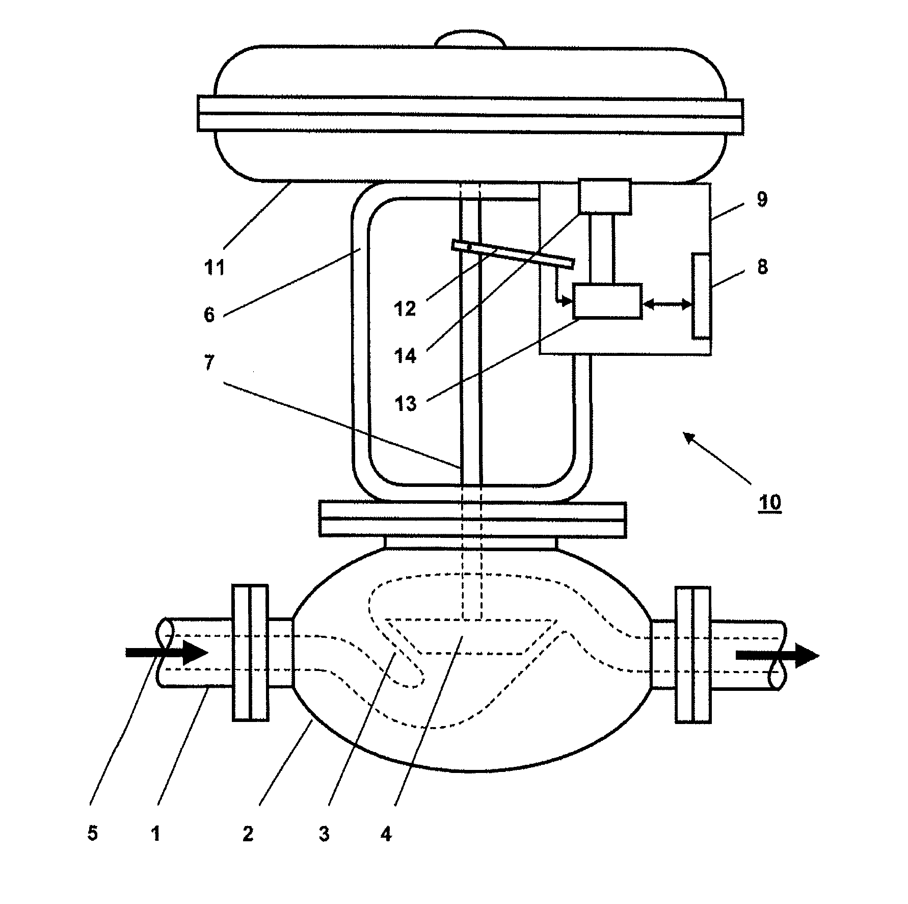
[0022]Exemplary embodiments of the present disclosure provide a method for determining the electronic wear state of the valve mechanism of a pneumatic actuating drive. The exemplary method provides reliable forecast results for future wear limits or instances of failure with the aid of simple electronic components.

[0023]According to an exemplary embodiment of the present disclosure, an I / P converter of the pneumatic actuating drive ensures a constant opening cross section at least over a portion of the switching stroke. At the constant opening cross section, a position sensor system determines time(s) at which various positions of the valve element are reached along the ventilating and / or venting distance, and this time is used to mathematically derive the speeds of the valve element prevailing at these positions by means of an evaluation unit. The change profile of the derived speeds represents a measure of the wear state.

[0024]An advantage of the solution according to exemplary em...


PUM


Abstract

A method is provided for determining the electronic wear state of a valve arrangement for controlling a process medium flow. A valve element is arranged to move axially within a valve housing, is reset by a spring, and is moved by application of control pressure via an I / P converter. The I / P converter ensures a constant opening cross section at least over a portion of the switching stroke, in the case of which the time at which various positions of the valve element along the ventilating and / or venting distance are reached is determined by means of a position sensor system, and this time is used to mathematically derive the speeds of the valve element prevailing at these positions by means of an evaluation unit. The change profile of the speeds represents a measure of the wear state of the valve mechanism.

Description

RELATED APPLICATIONS[0001]This application claims priority under 35 U.S.C. §119 to German Patent Application No. 10 2009 022 891.8 filed in Germany on May 27, 2009, the entire content of which is hereby incorporated by reference in its entirety.FIELD[0002]The present disclosure relates to a method for the determination of an electronic wear state of a valve arrangement, such as a pneumatic actuating drive, the valve element of said actuating drive, which valve element is arranged such that it can move axially within a valve housing and is reset by a spring, being moved by application of control pressure via an I / P converter. Furthermore, the disclosure also comprises a valve arrangement which has means for implementing a method of this kind.BACKGROUND INFORMATION[0003]The term “position regulator,” used in the present disclosure, represents a mechatronic system which controls the auxiliary energy of a pneumatic actuating drive on the basis of one or more input signals, in order to m...

Claims


Application Information

Patent Timeline
Patent Type & Authority Applications(United States)
IPC IPC(8): G06F19/00
CPCF15B19/00F16K31/1262F16K37/0041
Inventor MEIER, URS E.PAPE, DETLEF
Owner ABB TECH AG
Learn More