
Four wheel drive system

a four-wheel drive and steering system technology, applied in the direction of non-deflectable wheel steering, control devices, vehicle components, etc., can solve the problems of not providing four-wheel drive, none of these devices allowing a zero turn radius, etc., to reduce the number of pumps and their associated costs, reduce the complexity of integration and inefficiencies, and reduce the effect of cos

Active Publication Date: 2010-12-09
LAWSON JR THOMAS TOWLES
View PDF10 Cites 44 Cited by
  • Summary
  • Abstract
  • Description
  • Claims
  • Application Information

AI Technical Summary

Benefits of technology

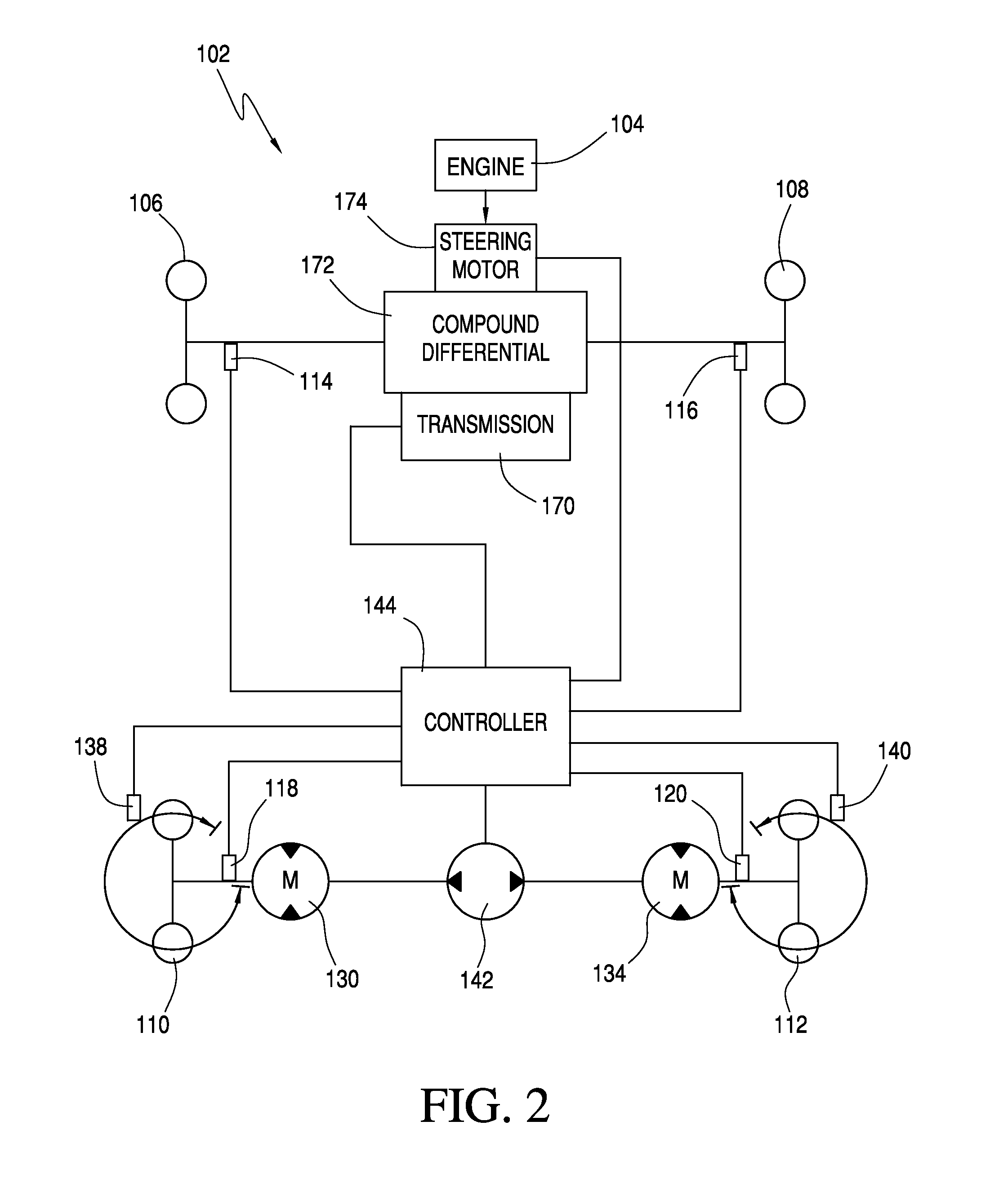
[0024]In an alternate configuration, the first drive system for the front wheels includes a power source, a power splitter connected with the power source, and a pair of opposed drive mechanisms connected with the power splitter and the front wheels. Each drive mechanism includes a first differential clutch connected with the power splitter and a second differential clutch connected with the first differential clutch. First and second braking devices are connected between the first and second differential clutches to control the delivery of power from the power splitter to each wheel. Operation of the first and second braking devices controls the degree and direction of driving power being delivered from the power source to the wheels. In a preferred embodiment, hydraulic pumps act as the braking devices and appropriate valves and controls avoid the need for separate pumps.
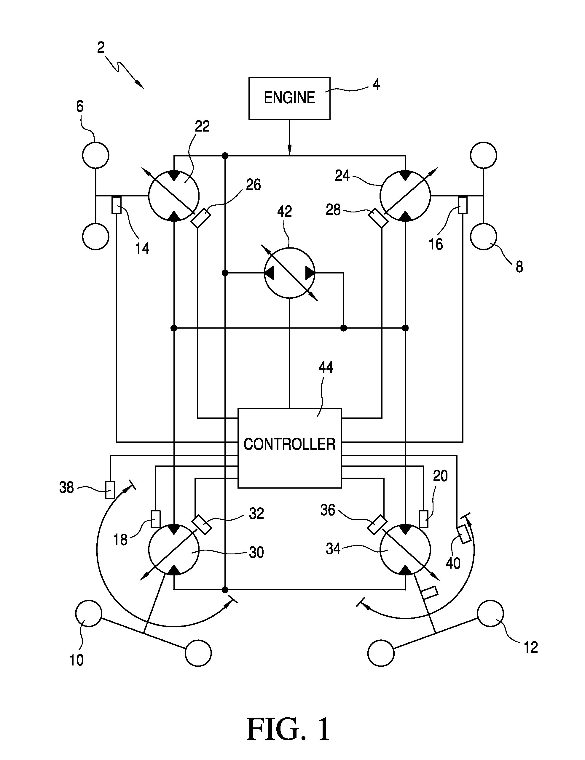
[0025]In another configuration the aim of which is to reduce the number of pumps and their associated cost, complexity of integration and inefficiencies, a single pump is fluidly connected to drive motors associated with each of the four wheels. A steering angle sensor or sensors detects the angle of each of the steering wheels and sensors detect speed and rotation of each wheel. The controller can change the angles of the drive motor swash plates to vary the speed, direction and torque of the motors for a given flow from the pump. In this configuration, one pump drives all of the motors in parallel. This pump can be either of two types.
[0030]Another distinction which needs to be made is between open and closed loop systems. Because circuit and loop have such similar definitions in the vernacular and are even used interchangeably in the art, this clarification is necessary. An open loop system is one where by design the controller does not receive feedback from the wheel and cannot determine whether a target speed is achieved. Closed loop means that a sensor of some type sends a signal which allows the controller to calculate whether a signal it sends causes the intended effect. An example of this from the current invention is that if it were made with four closed circuit hydrostatic pump and motor systems, one for each drive wheel, the controller would not need feed back from the wheels and could still be within a plus or minus 10% range on wheel speed because of the pump motor efficiencies. For at least one of the following preferred embodiments, closed loops are probably necessary because the controller has only one pump to control four wheels. The closed loops allow the controller to effectively control wheel speed independently of each other by changing the motor displacements. Traction and other variables like grade and steering angle require feedback on wheel speed to know whether fluid is going to the right place.

Problems solved by technology

However, other than skid steering, none of these devices allow a zero turn radius.
Moreover two wheel drive zero turning radius vehicles known in the art are not provided with four wheel drive because of the complexities of driving the steering wheels as set forth above.

Method used


Image

  • Four wheel drive system
  • Four wheel drive system
  • Four wheel drive system

Examples


Embodiment Construction

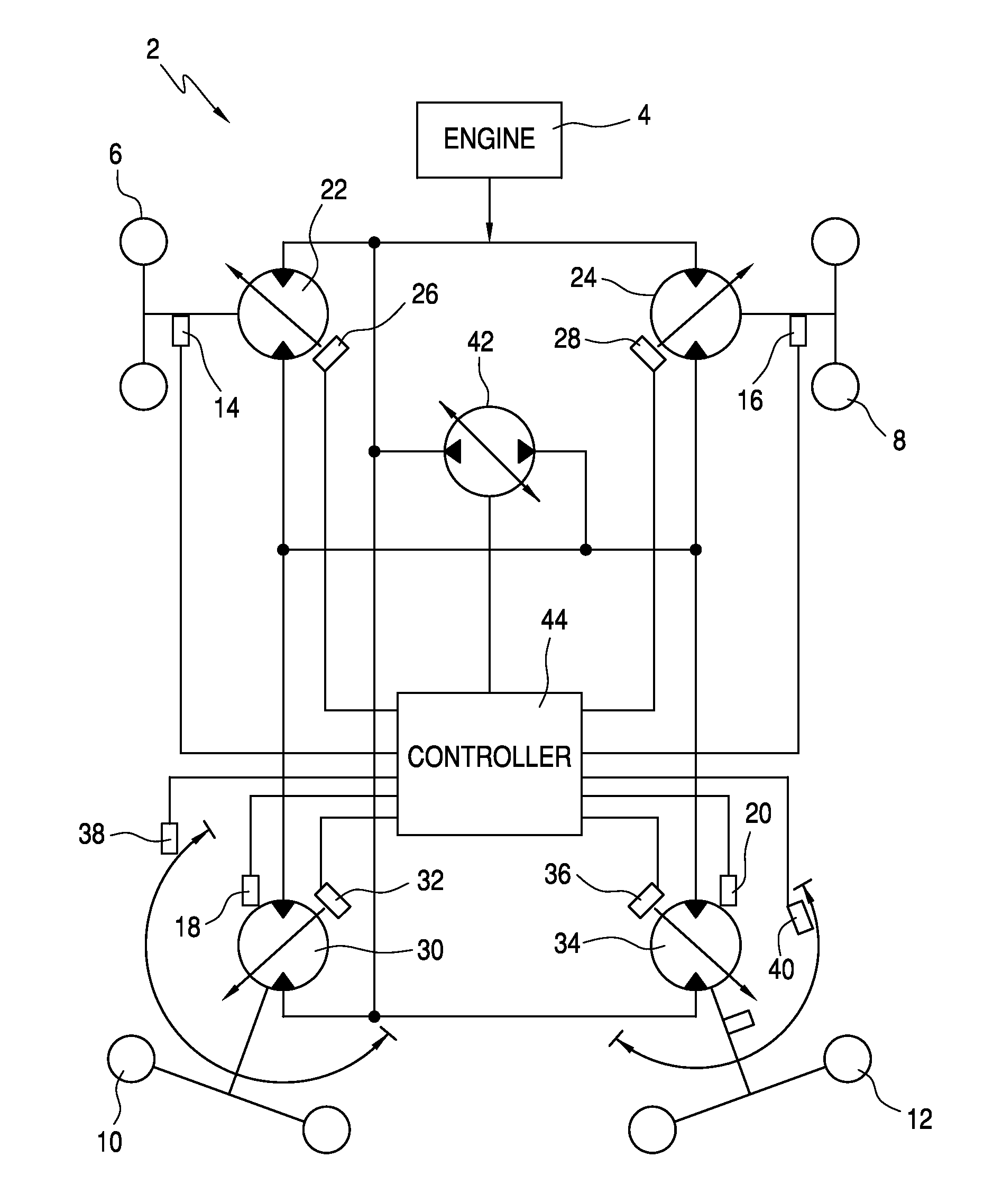
[0040]Referring to FIG. 1, the four wheel drive system according to the invention will be described. The vehicle 2 includes an engine 4 which provides power to propel the vehicle and for the various components of the vehicle drive system. In addition, the vehicle includes non-steerable left 6 and right 8 front wheels and left 10 and right 12 steerable rear wheels. Although wheels are shown, it will be apparent to those of ordinary skill in the art that the wheels can be replaced with tracks or other rotatable devices. Wheel speed sensors 14, 16, 18, and 20 are provided for each of the wheels 6, 8, 10, and 12, respectively.

[0041]The drive system includes a variable displacement overcenter motor 22 for the left non-steer wheel 6 and another variable displacement overcenter motor 24 for the right non-steer wheel 8. A servo controller 26 is provided for the left overcenter motor 22 and a servo controller 28 is provided for the right overcenter motor 24.

[0042]The drive system further inc...


PUM


Abstract

A four wheel drive system for bilaterally symmetric vehicles has separate controlled drive speed and direction for each wheel. Each drive system is operable to independently drive each wheel. The rear wheels of the vehicle are steering wheels which are connected with the vehicle frame for independent rotation about a vertical axis. Steering and driving of the wheels is controlled by a controller. The combination of controlled steering for the rear wheels through many degrees about their vertical axes and individual power to all four wheels provides the vehicle with a zero turning radius for improved mobility as well as improved traction on unstable surfaces.

Description

[0001]This application claims the benefit of U.S. provisional application No. 61 / 184,133 filed Jun. 4, 2009.BACKGROUND OF THE INVENTION[0002]Designers of vehicles, particularly heavy equipment vehicles, tractors, and the like have always had to decide whether traction or maneuverability was the more important quality in a given machine. Tractors at one time were generally not considered for four wheel drive systems because it was believed that deliberate weight distribution and bilaterally independent brakes on the drive wheels would be sufficient for maximum tractive force and directional control. Moreover, there are difficulties in providing a driving force to the front steering wheels of such vehicles. If the steering wheels are given drive capability, it is be advantageous to make the steering wheels larger for greater traction. However, larger front steered wheels interfere with the framework of the vehicle, thereby limiting their usefulness. In addition, conventional different...

Claims


Application Information

Patent Timeline
Patent Type & Authority Applications(United States)
IPC IPC(8): B60K17/356B62D11/06
CPCB60K17/356B62D11/001B62D11/04B62D11/24B62D11/06
Inventor LAWSON, JR., T. TOWLES
Owner LAWSON JR THOMAS TOWLES
Learn More