Variable ratio crank for a manual flight control linkage of a rotary wing aircraft

a flight control and variable ratio technology, applied in the direction of propellers, aircraft transmission means, propulsive elements, etc., can solve the problems of hybrid helicopters being subjected to an increased risk of exceeding their structural and/or flying limits, automatic nose-up attitude,

Active Publication Date: 2010-12-09
EUROCOPTER
View PDF12 Cites 33 Cited by
  • Summary
  • Abstract
  • Description
  • Claims
  • Application Information

AI Technical Summary

Benefits of technology

[0085]From the above, it can be understood that with an interlink interposed between the two sliders, the gain adjustments represented by changes in the length of the inlet (upstream) and outlet (downstream) radii ta

Problems solved by technology

Because of the high air speeds that can be achieved by a hybrid helicopter, its airfoils for changing flight attitude are highly stressed, thus making it necessary to provide power assistance in order to enable them to be moved manually.
Such a risk arises when the structural and/or functional limits concerning flight are reached while performing an operation for changing a flight attitude.
Thus, with power-assisted manual flight controls, it is sometimes necessary to be able to vary the gain of a manual control device such as a stick, a lever, or a rudder bar, for example.
A hybrid helicopter is thus subjected to an increased risk of exceeding its structural and/or flying limits, in the event of a manual flight control being operated too hard in the absence of any limit on its gain.
One of the risks involved involves automatically taking a nose-up attitude.
Because of the high air speeds that can be achieved by a hybrid helicopter, its airfoils for changing flight attitude are highly stressed, thus making it necessary to provide power assistance in order to enable them to be moved manually.
Although of interest, those prior art techniques are in practice poorly adapted to the very particular context of adjusting the gain of certain manual flight controls in a rotary wing aircraft, in particular a hybrid helicopter, in proportion to a piloting parameter.
At forward speeds greater than those of a conventional rotary wing aircraft, it is particularly complex in practice to provide the functional balancing needed for optimizing the flight of such a hybrid helicopter.
With power assist

Method used


Image

  • Variable ratio crank for a manual flight control linkage of a rotary wing aircraft
  • Variable ratio crank for a manual flight control linkage of a rotary wing aircraft
  • Variable ratio crank for a manual flight control linkage of a rotary wing aircraft

Examples


Embodiment Construction

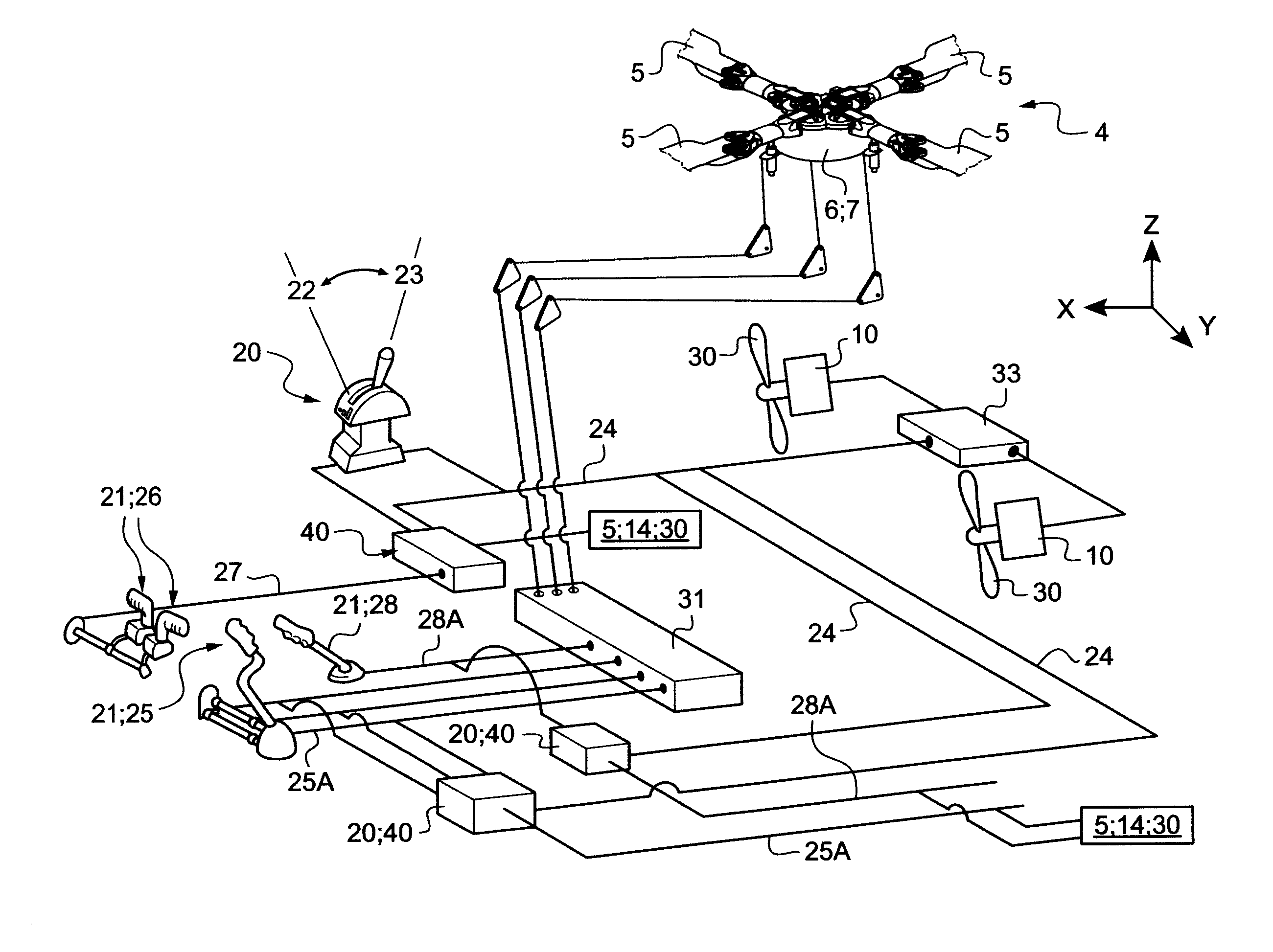
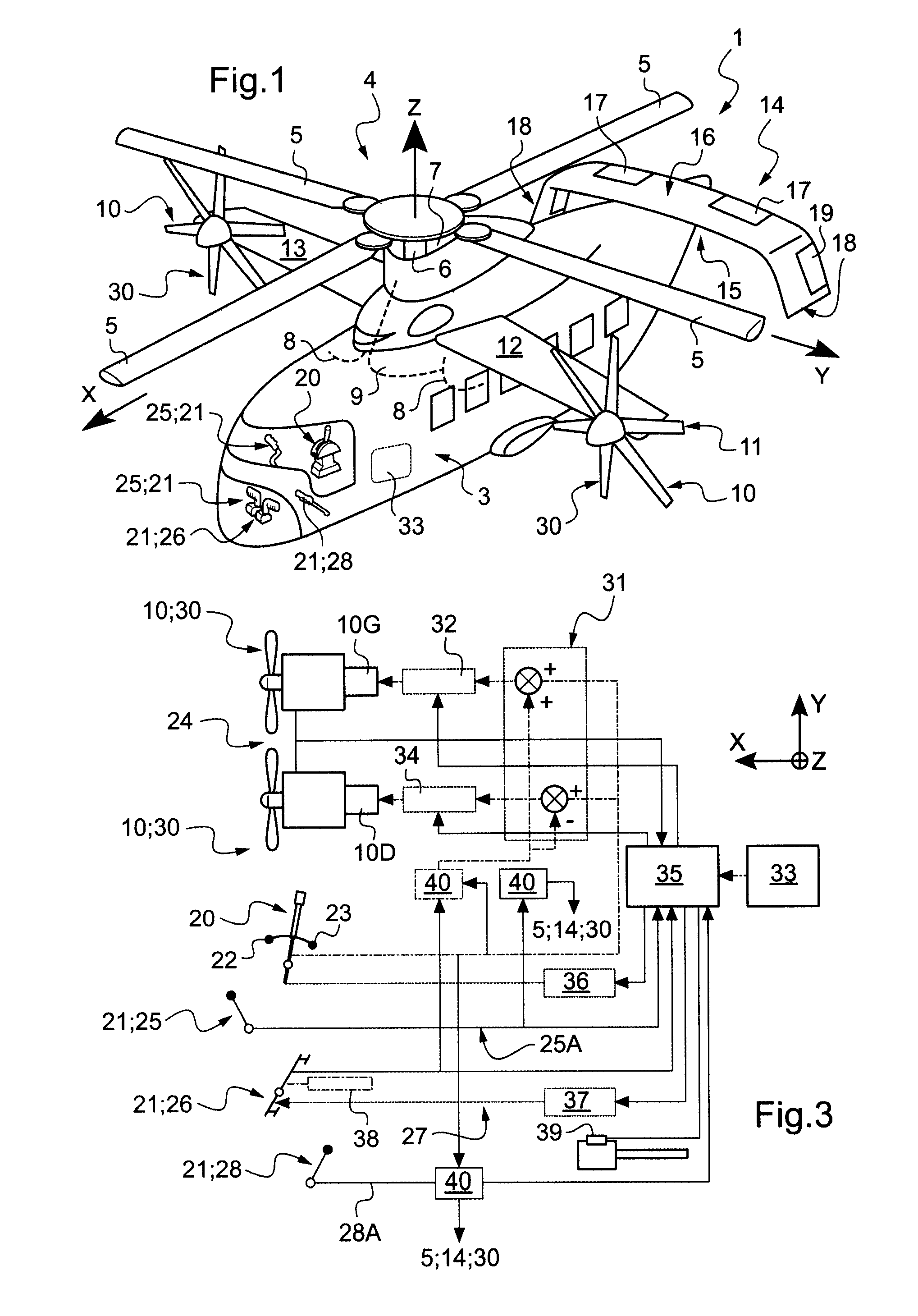
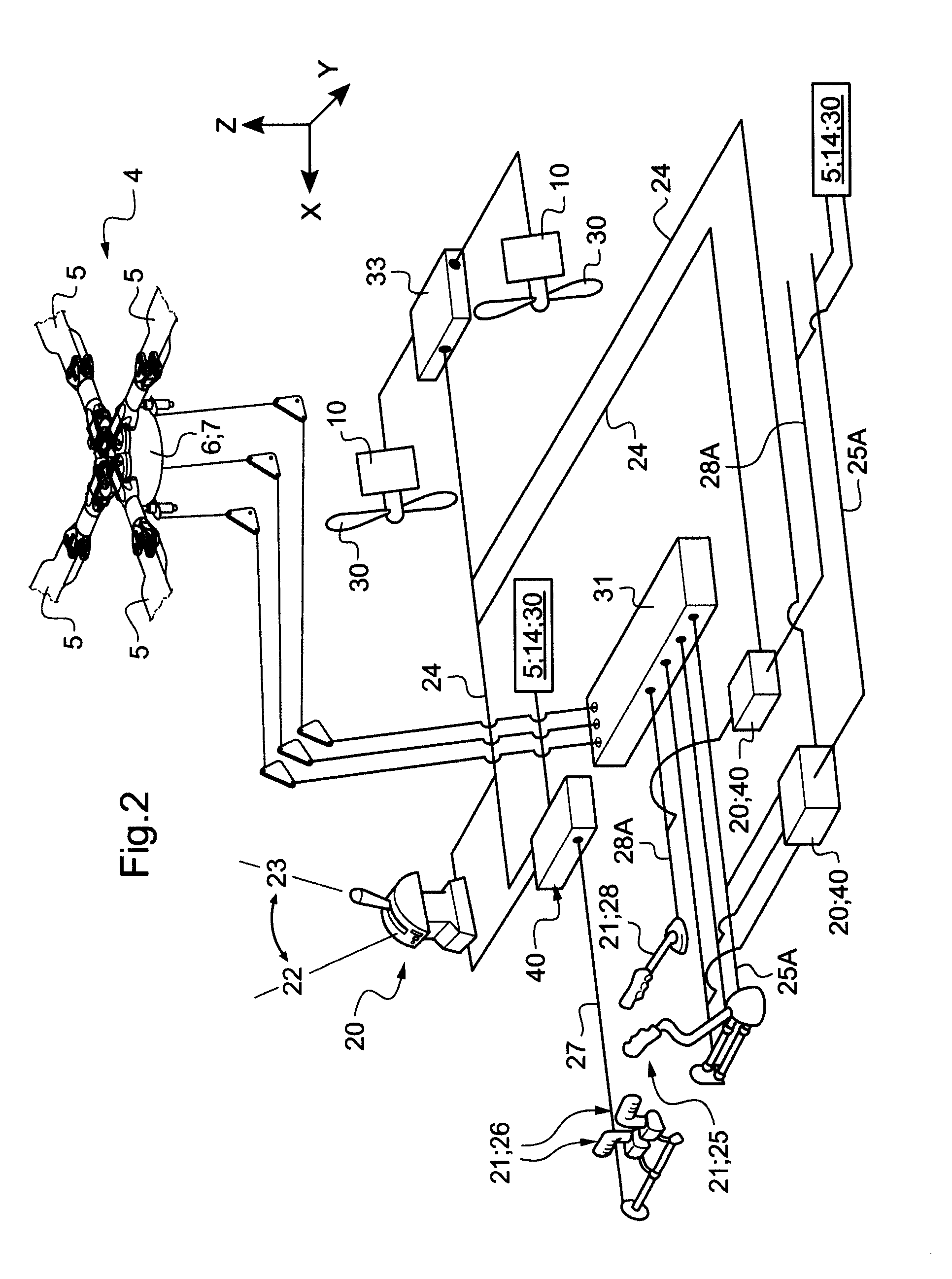
[0100]The figures show three mutually orthogonal directions X, Y, and Z.

[0101]A “longitudinal” direction X corresponds to the lengths or main dimensions of the structures described. Thus, the forward thrust or the main component of the air speed on a level flight path is directed in this direction X.

[0102]In aviation, it is common for this direction X to designate generally the roll axis of the aircraft, when the aircraft is considered as a whole.

[0103]Another direction, Y, is said to be “transverse”, and corresponds to the lateral widths or dimensions of the structures described. These longitudinal and transverse directions X and Y are sometimes said to be horizontal, by way of simplification. For example, the distance from the fuselage of a propulsion arrangement is generally measured along this direction Y.

[0104]In aviation, it is common for the direction Y generally to designate the pitch axis of the aircraft. It is also this direction Y that is used to define the terms “left” (...


PUM


Abstract

The present invention relates to a bellcrank (40) for a flight-attitude-changing linkage (27, 25A, 28A) of the variable gain type. The linkage (27, 25A, 28A) connects a manual flight control device of a rotary wing aircraft (1), e.g. a hybrid helicopter, to at least one airfoil of said aircraft (1) suitable for causing a change in flight attitude. Said bellcrank (40) includes first and second sliders (50, 52). Said first slider (50) is connected to a movable portion (57, 61) of a setpoint flight-attitude-changing linkage (24) that delivers a setpoint, with movements of said linkage causing the gain of said variable-gain linkage (27, 25A, 28A) to be adjusted, which gain is proportional to the position of said movable portion (57, 61).

Description

CROSS REFERENCE TO RELATED APPLICATIONS[0001]This application claims the benefit of FR 09 02685 filed Jun. 4, 2009. The disclosure of which is incorporated in its entirety by reference herein.FIELD OF THE INVENTION[0002]The present invention relates to a crank having a variable ratio transmission in a manual flight control that acts on a linkage suitable for giving rise to flight attitude changes in a rotary wing aircraft.BACKGROUND OF THE INVENTION[0003]Although not limited thereto, the invention is described in its applications to a helicopter of the hybrid type, e.g. as described in documents FR 2 916 418, FR 2 916 419, and FR 2 916 420.[0004]That hybrid helicopter associates, at reasonable cost, the effectiveness in vertical flight of a conventional helicopter with high-speed performance in horizontal flight, e.g. up to a cruising air speed of about 400 kilometers per hour (km / h) or even more, and indeed also with a greater range.[0005]For reasons of simplicity, the term “rotary...

Claims


Application Information

Patent Timeline
IPC IPC(8): B64C13/38
CPCB64C13/28B64C27/22B64C27/58B64C27/56B64C27/26
Inventor GEMMATI, BERNARDBIEST, ROMUALDMIRMAN, CARINE
Owner EUROCOPTER
Why Eureka
Try Eureka