Filter Assembly

a filter and assembly technology, applied in the field of filters, can solve the problems of inability to replace the dielectric rod, limited power handling capability, and inability to achieve the te01d mode at 1.9 ghz frequency, and achieve the effects of reducing scrap cost, less tolerance sensitive, and small filter assembly

Active Publication Date: 2010-12-09
TELEFON AB LM ERICSSON (PUBL)
View PDF9 Cites 23 Cited by
  • Summary
  • Abstract
  • Description
  • Claims
  • Application Information

AI Technical Summary

Benefits of technology

[0022]An advantage of the present invention is a potential drastic reduction in scrap cost since the dielectric rods can be replaced individually since the dielectric rods are attached using fastening elements and not soldering.
[0023]A further advantage of the present invention is that the filter assembly design is less tolerance sensitive due to the conductive element of the dielectric rod.
[0024]Another advantage of the present invention is the scalability enabling significantly smaller filter assemblies compared to prior art. This is due to the replaceable dielectric rod.
[0025]A further advantage of the present invention is a more repeatable soldering of the dielectric rod is possible due to the fact that each dielectric rod may be soldered separately / individually.

Problems solved by technology

One disadvantage with ordinary coaxial resonators may be the limited power handling capability, which is caused by the small gap between the resonator and the tuning element.
Smaller cavity size with TE01d mode at 1.9 GHz frequency is not possible, because it is then necessary to increase the puck diameter.
A problem with the existing solution, using soldering to attach the TM mode dielectric rods to the filter housing and / or the lid, is that once the dielectric rod have been assembled and soldered, the dielectric rod cannot be replaced.
In practice, this is however not possible, due to the fact that the conductive plating material, such as e.g. the silver plating, at the dielectric rod ends will only be good for one soldering operation, thus the dielectric rod is not replaceable.
However, frequency tuning performed by removing material is irreversible, i.e. the frequency tuning can only be performed in one way.
This involves a considerable risk that too much material is removed which makes the dielectric rods and the whole ceramic filter accordingly of less use and most probably even useless.
Secondly there is a considerable risk that the dielectric rods are damaged.
Today it is not possible to add material that has been removed, or repair a dielectric rod that has been damaged.
The result of this is a potentially very high scrap cost since the whole filter has to be scrapped if one single frequency tuning operation fails.
However a disadvantage of this method is that the hollow and the tuning screw will decrease the filter performance, i.e. lower the Q factor, and also reduce the power handling capability.
A further disadvantage of the existing solutions of grounding the dielectric rod ends by soldering is that it is difficult to get a repeatable soldering process for a complete filter consisting of several dielectric rods when soldering directly to the filter housing and the filter lid.
This is because of the product mass of the filter housing and filter cover being high which causes the filter housing, filter cover and ceramics to heat up slowly which delays the soldering considerably.
This may further have a negative effect on the long term solder joint reliability.
When the whole filter assembly is heated, it is also required that all components inside the product can withstand the soldering temperature; this will limit the choice of material, such as e.g. plastics, and possibly also increase the material cost.
A high mass product is also difficult to handle after the soldering operation because of the latent heat in the filter housing, lid and ceramics, thus the cool down process has to be long, which increases the manufacturing lead time and cost.
Further the multiple solder joint orientations, such as e.g. two directions in the case of a TM single mode filter or four in the case of a TM dual mode filter, complicates the soldering process.
Moreover, when soldering directly to the filter housing and lid it is necessary to have tight mechanical tolerances, and that is also cost driving.

Method used


Image

  • Filter Assembly
  • Filter Assembly
  • Filter Assembly

Examples


Embodiment Construction

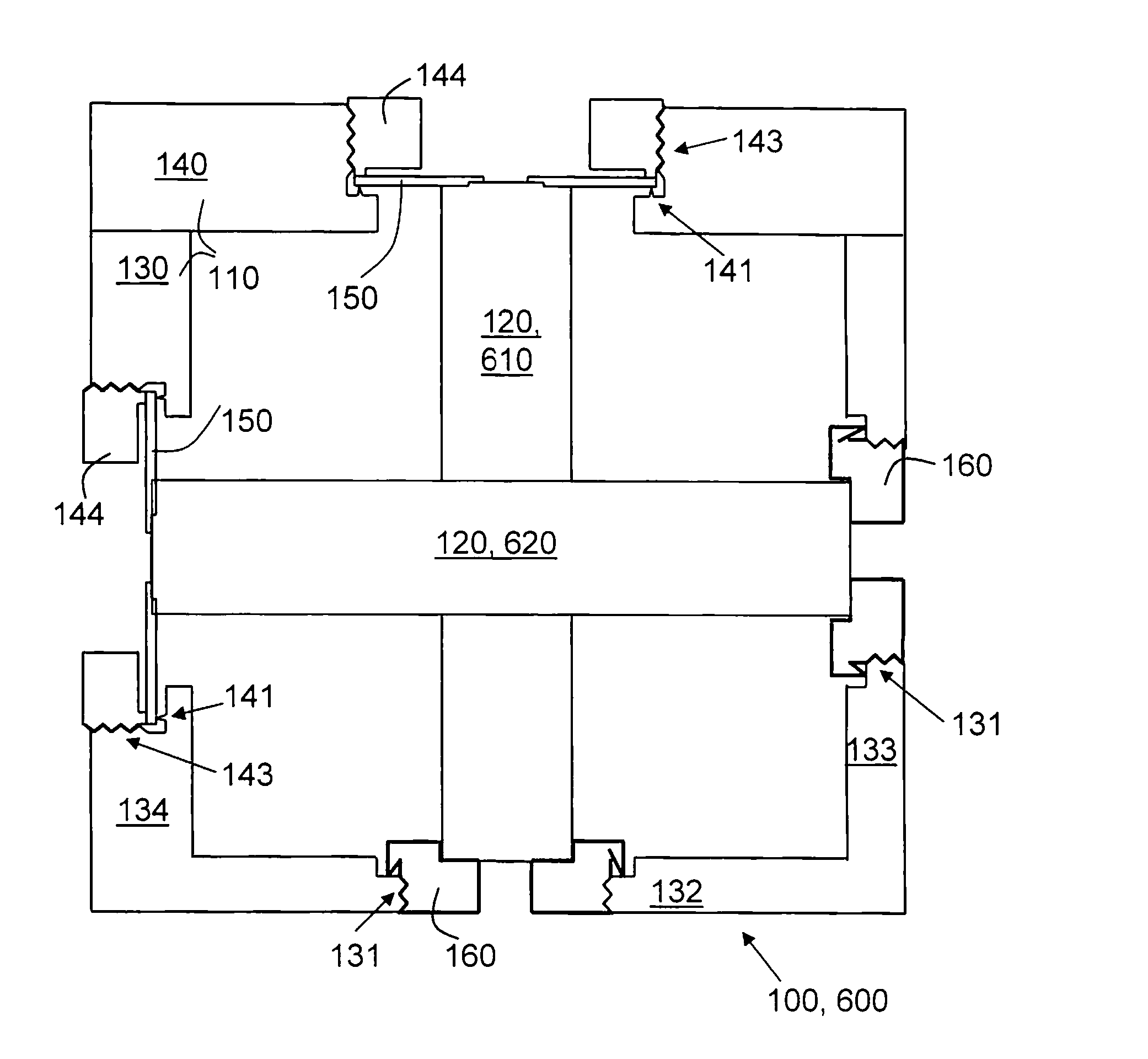
[0033]The invention is defined as a filter assembly which may be put into practice in the embodiments further described below.

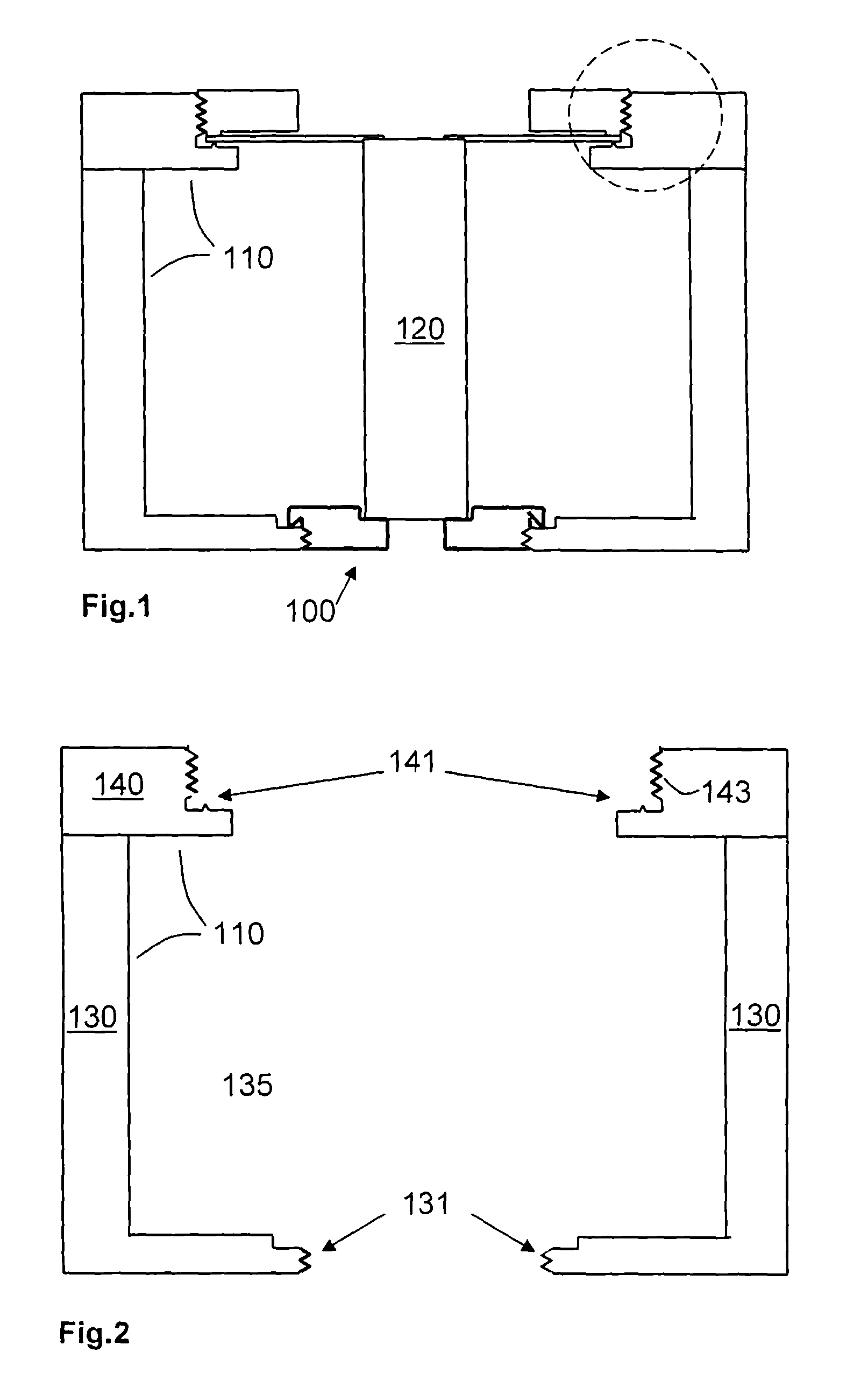
[0034]FIG. 1 presents a cross section of a filter assembly 100 according to some embodiments of the invention. The filter assembly 100 comprises a filter chassis 110 and at least one dielectric rod 120. The filter assembly 100 according to the present solution may comprise a plural of dielectric rods 120, such as e.g. as many as 30. However, only one dielectric rod 120 is depicted in FIG. 1. The filter assembly 100 may be a TM single mode resonator.

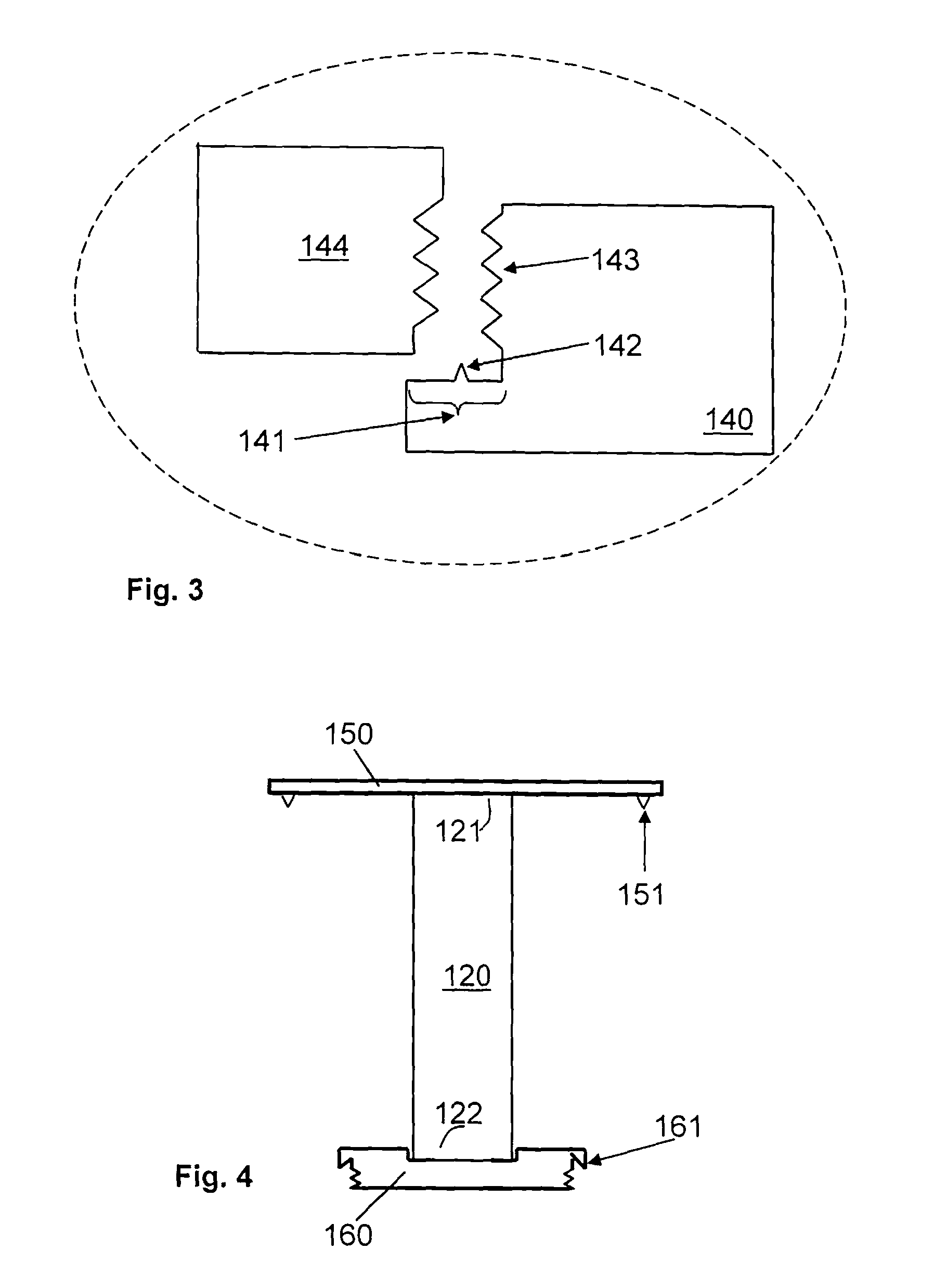
[0035]FIG. 2 depicts a cross section of the filter chassis 110. The filter chassis 110 may comprise a filter housing 130, a filter cavity 135 and a filter cover 140. Examples of filter covers 140 are e.g. a lid, cap, cover. The filter housing 130 may be adapted to be arranged together with the filter cover 140. The filter housing 130 and filter cover 140 may be made of e.g. silver plated copper on aluminum. The fil...


PUM


Abstract

An object of the present invention is to provide an improved and simplified filter assembly. The object is achieved by a dielectric rod (120, 610, 620) for a filter chassis (110). The dielectric rod (120, 610, 620) extends between a first end (121) and a second end (122). The dielectric rod (120, 610, 620) comprises a conductive element (150) placed at the first (end 121). The conductive element (150) is adapted to be in conductive contact with a first contact means (141) of the filter chassis (110). The dielectric rod further comprises a second fastening element (160) placed at the second end (122). The second fastening element (160) is adapted to be attached and detached to a first fastening element (131) comprised in the filter chassis (110), such that the dielectric rod (120, 610, 620) is replaceable in the filter chassis (110).

Description

TECHNICAL FIELD[0001]The present invention relates to the field of filters. More particularly the present invention relates to a dielectric rod, a filter chassis, a filter assembly as well as a radio transmission device comprising such a filter assembly.BACKGROUND[0002]Filters are circuits which may be used in communication systems to compensate for disturbances such as e.g. interference, etc. caused by the nature of the transmission media between sender and receiver. Filters remove the unwanted communication signal components and / or enhance the wanted communication signal components.[0003]Radio Frequency (RF) filters and Microwave filters represent a class of filters, designed to operate on signals in the Megahertz to Gigahertz frequency ranges. This frequency range is the range used by most broadcast radio, television and wireless communication systems such as e.g. cellular communication systems, Wi-Fi, WiMax, LTE, etc. Thus most wireless communication devices will include some ki...

Claims


Application Information

Patent Timeline
Patent Type & Authority Applications(United States)
IPC IPC(8): H01P1/20H01P7/10
CPCH01P7/10H01P1/2084
Inventor MYLLYVAINIO, ESAGUSTAFSON, BENNY
Owner TELEFON AB LM ERICSSON (PUBL)
Why Eureka
Try Eureka